
1/48 Airfix Supermarine Type 356 / Spitfire F Mk 21:
100% Airfix, almost!
As a kid it was impossible to find a Griffon-engined Spitfire model: my local newsagent only stocked Airfix kits! It is not surprising then to find I am having some sort of throw back desire to add that sleek nosed airframe to my collection. In fact, almost every Spitfire I’ve built of late has been a Griffon version. [Actually just finished an Airfix new-tool Mk Vb – see here.
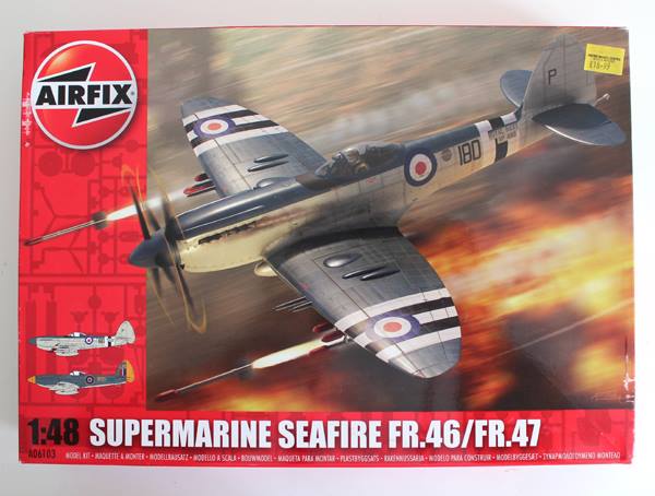
My desire to build more has not lessened and I’ve now accumulated a collection of Spitfire spare parts for my spares box, the most notable ‘spare’ components being a set of Seafire 46 wings – suitable for any late mark Spitfire! These wings can’t be wasted so the time has come to build that hybrid throw-back which is the Spitfire F.21.
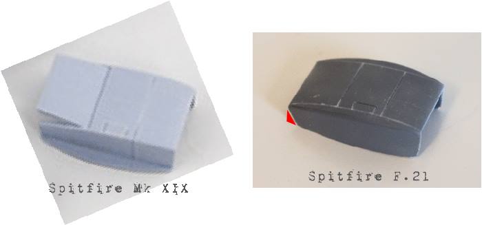
The Spitfire F.21 retained the high-back fuselage of the mark XIVc and combined the newest stiff wing design featured in the last Spitfire and Seafire versions. My intent is to build an F.21 from these left over ’46 wings and combine them with Airfix’s new Spitfire Mk XIX release. The resultant model will be 100% Airfix!!
My goal:
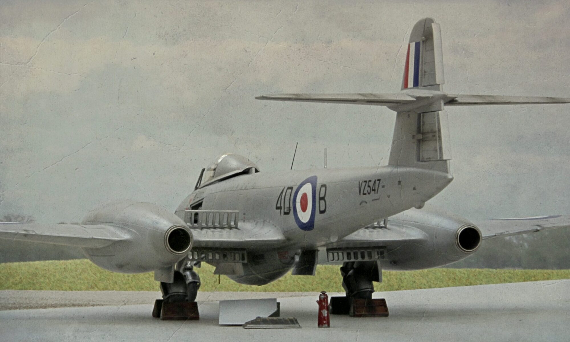
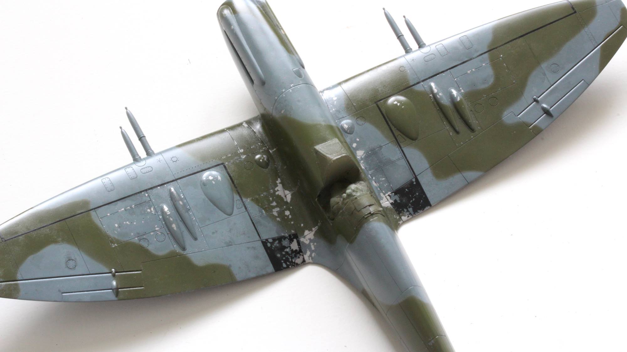
Most operational airframes I see when studying WWII photos, those long-in-the-tooth, drab grey/green, piston fighters – and who wouldn’t rather fly a nice new shiny silver jet with bright red white and blue markings?- seem faded, stained and very worn. As well as trying to recreate one of the last RAuxAF’s Spitfire Mk 21s, just prior to their conversion to sleek high-speed-silver Meteors, I’ll be attempting to recreate that same time-worn, faded and blotchy look of a well used operational machine.
In particularly, I intend to focus on two specific modelling aspects; keeping my chipping down and, practising my airbrushing to create that very faded and blotchy appearance.
This thread:
I am sure most, if not all of you, have built a Spitfire before so you don’t need me to write a detailed and fully sequenced account of the build. I’m just going to focus on what steps I took to create my F.21.
The kits:
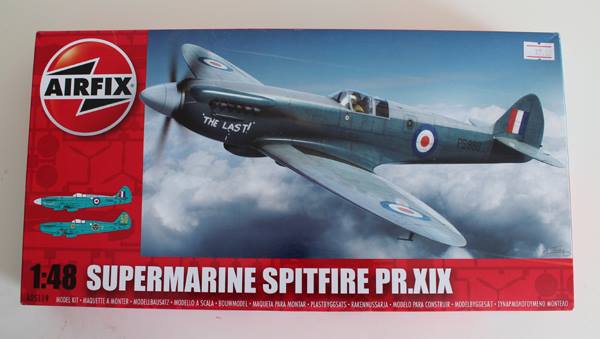
Having made a couple of Spitfire XIX kits already, I have to admit, I’ve fallen in love with this kit – for the price! It is not a perfect kit. It does suffer from some sink marks and ejector pin issues, its detail is a little soft around the cockpit walls and the panel lines may be considered too deep. But oh; oh what a lovely profile!
It becomes obvious quickly that this kit has a smashing ‘Mk XIV’ or ‘late 2-stage Griffon’ profile, ripe for use elsewhere. The relatively low cost of this kit makes it a useful donor for any 2-stage Griffon ‘fire airframe: given that the Acadamy kit has such a poor profile and the Aeroclub conversion kit seems hard to come by and expensive.
Since the Mk XIX was basically a Mk XIV airframe the kit lends itself for any early high-back Mk XIVc or XIVe and, if you fancy wielding the razor saw, the front and tail ends would provide the best parts for a nice low-back MkXIV or even a contribution toward a Mk XVIII. In my case, I will use the whole fuselage for my F.21.
The Seafire kit is older and unlike the Airfix XII, XVII and XIX it does not seem to share the same base dimensions. The XII, XVII and XIX fuselages all match up dimensionally together and the XII and XVII are almost a perfect fit. The Seafire 46/47 doesn’t fit these other kits as well. Anything used from the 46/47 kit will require some fettling as if one was using a kit from another manufacturer. Anyway, it is a fair kit and most importantly, it leaves you with a spare pair of Seafire 46 (or Spitfire MK 22/24) wings.
Photographic Observations:
While doing some research on the F.21 (internet trawling mostly) a few things come to light… (by the way, if I’ve got something wrong here, please let me know)…
- In order to improve the C.of G. position, the radio equipment seems to have been moved further back in the fuselage. The normal rear radio hatch on the port side is omitted in favour of one further back on the starboard side – one fuselage frame further back even than starboard camera hatch on the Mk XIX.
- Some F.21s appear to have the Mk XVIII-style rudder; a slightly modified shorter fin with a taller and broader rudder. This modified rudder also has a kinked and notched trim tab similar to that of the Mk 22/24. All my photographs of contra-prop airframes show a ‘Mk XVIII’ fin/rudder while the five-bladed versions seem to have a standard Mk XIV rudder.
- There seems to be a mix of 3- and 4-spoke wheel rims in use on the F.21. The mod to change them must have been issued sometime in the operational life span of the F.21.
- The radiator tubs are wider with a more curved plan view, and slightly different in profile, than those provided in the Mk XIX kit.
- Some 3-view artwork shows extended span horizontal tailplanes, similar to the Mk 22/24 airframe (which had the so called full ‘Spiteful’ tail – which included larger horizontal tail, fin and rudder). I could find no photographic evidence that the F.21 had the larger horizontal tail. As far as my photos show, where they do show, the horizontal tailplane looks standard. To my understanding, tail modifications employed to cure handling and stability issues with early 21s took the form of configuration changes to rudder and elevator control mechanisms and changes in elevator balancing.
- Exhaust studs appear to be horizontal and tubular. Early war-time machines appear to have ‘fish-tail’ type stubs – notably the prototype. At least one photo shows a contra-prop machine, with XVIII-style rudder, having downward angled 6-stub tube exhausts (wearing squadron codes ‘GO-G’).
- Recognition/signal lamps; the second production machine seems lacking in any lamp (either the old-style single central fuselage lamp, the later Mk XIV single more rearward lamp, the Mk XIV wing-mounted lamps or the later bank of three down the fuselage). But the F.21 machine that was hanging in the museum in Glasgow clearly shows the later style bank of three.
- Gun camera port; on the Glasgow machine this appears in the starboard wing root (same as the F.24 at Hendon).
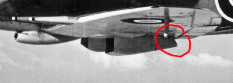
- Fitting of hooks for attachment of long-range belly tanks; I only have one photo, head on, that shows anything that remotely looks like these hooks – and it is difficult to see. I have no photos showing a long range tank fitted (odd since I have plenty of F.22 photos with hooks only or hooks with tank fitted).
- Beam approach aerial; not seen in any photos of the F.21. This seems to disappear with the F.21. (F.22 prototype PK312 being an exception).
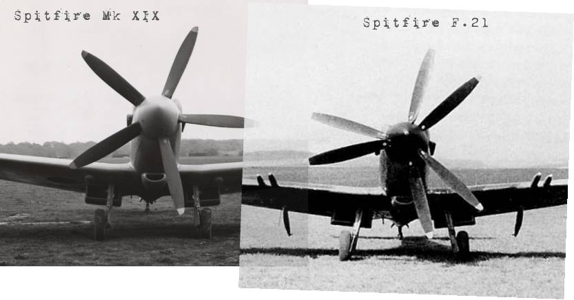
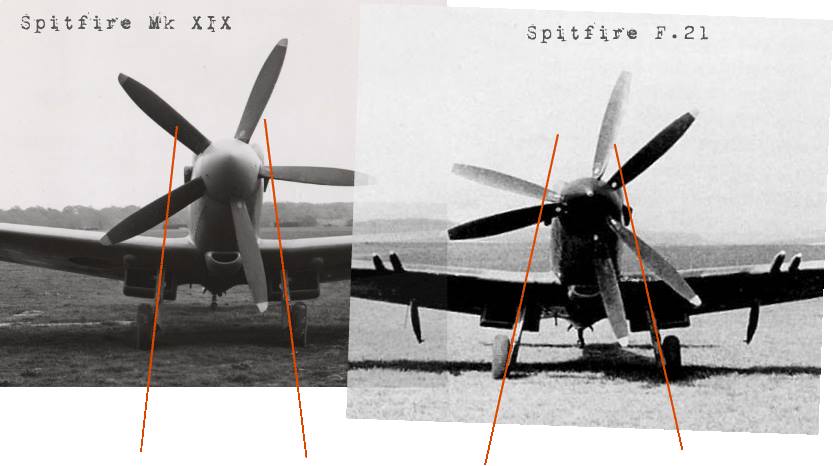
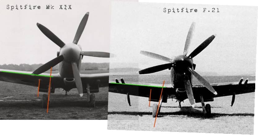
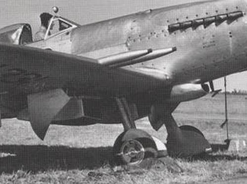
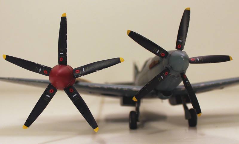
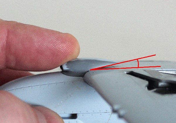
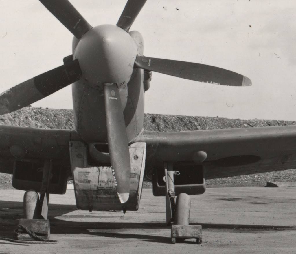
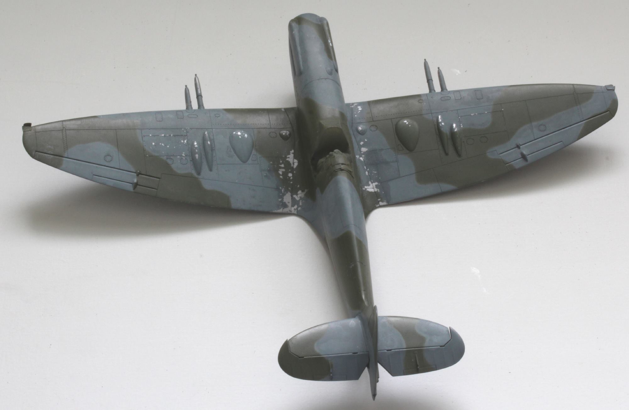
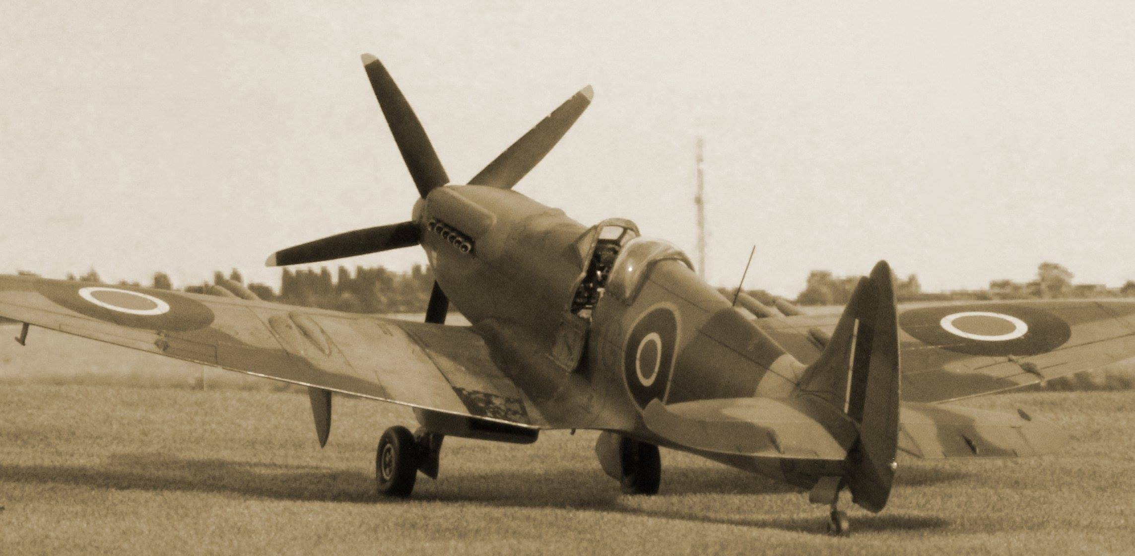
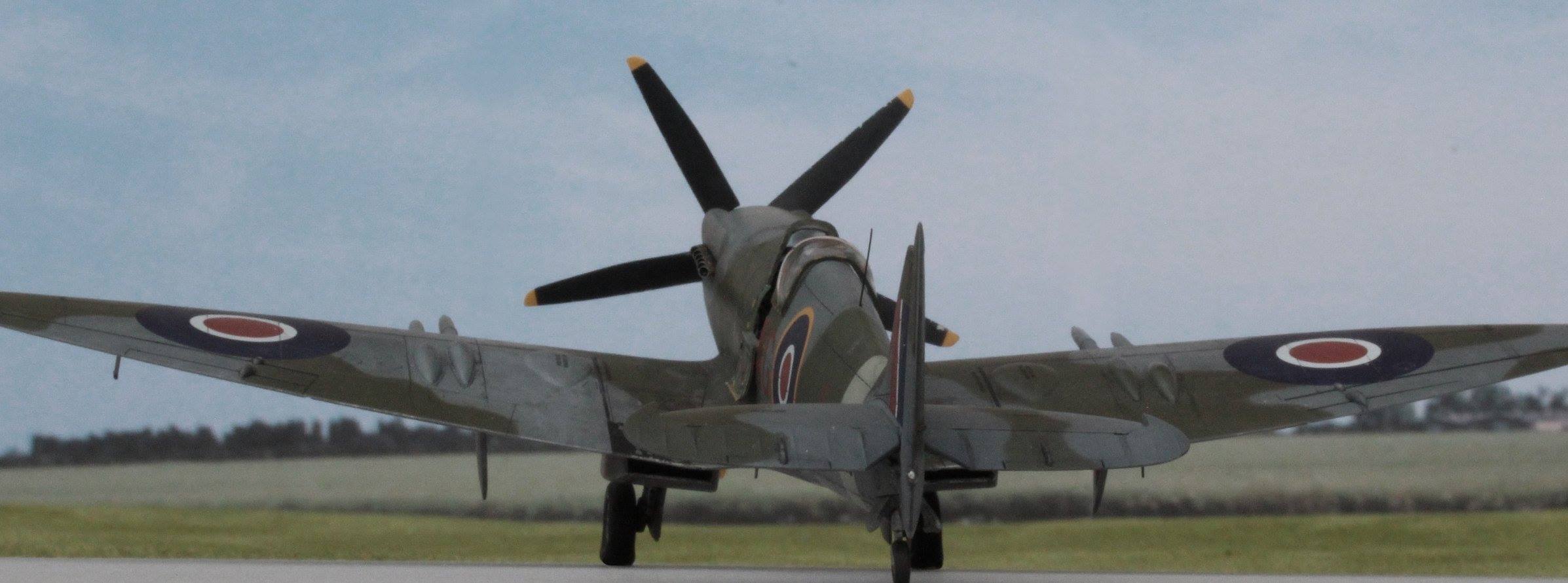
- Undercarriage geometry; my understanding is that the main gear oleo was lengthen around 2.4mm at 1/48 scale. Yet the F.21s don’t appear to sit nose high. The prop diameter was increased to 11 feet on 21s from 10 foot 5 inches on XVIIIs and XIXs. This is an increase of 3 inches on the radius – about 1.5mm at scale. That is, ground clearance was reduced by 3 inches. In my view, the reason the 21 doesn’t look like it’s nose is in the air with their longer legs is due to the change in undercarriage geometry. Looking head-on at the airframe the main gear looks far more ‘splayed’ out from the centre than previous marks. Splaying out the gear, or widening the wheel track helps stability but will also lose some height through simple trigonometry. Despite this angle change, the wheels still retain that classic slightly positive camber angle. Here’s a series of photos comparing the XIX and 21 from the front. You can see the relative angles between oleo, leading edge and radiator tub walls.
Getting on with the job:
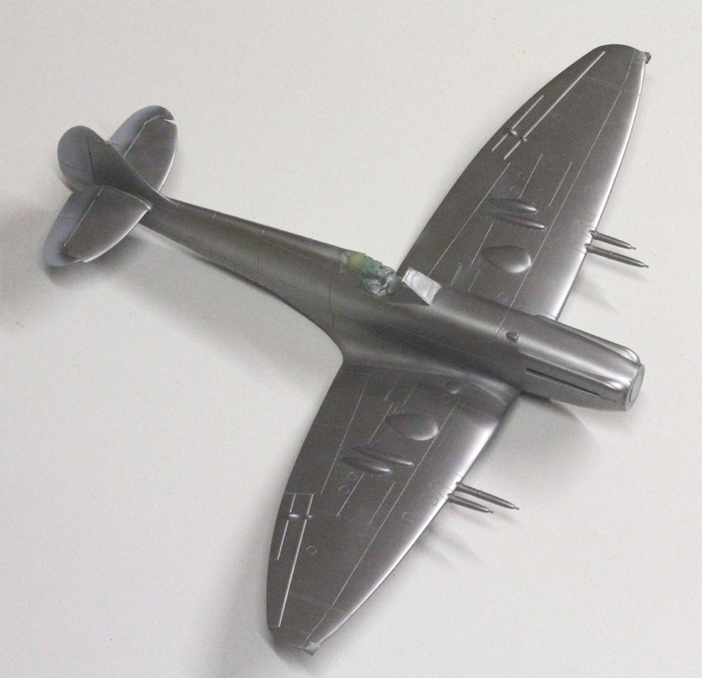
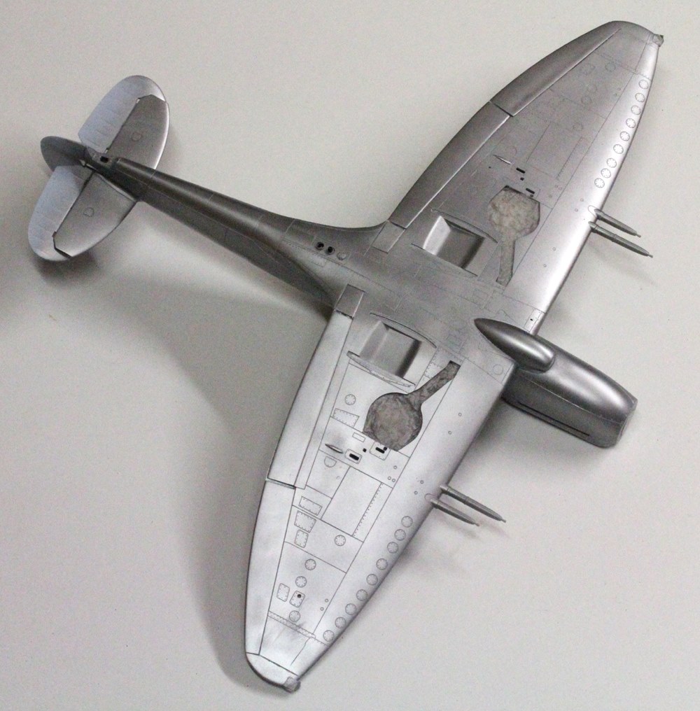
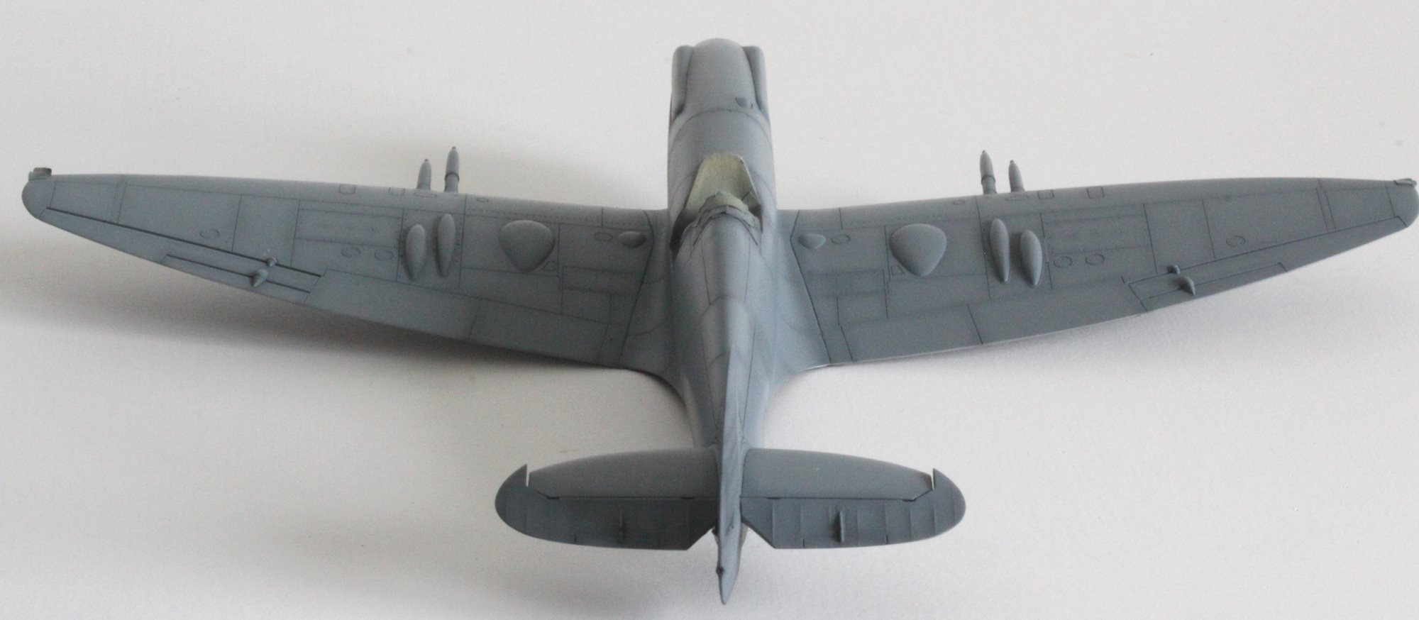
On first look, offering up wings and fuselage, one can see the fit isn’t perfect. Viewed from above, the wide, flat and on-its-side ‘V’ shape of the wing root joints are not the same between the two kits. The apex of the ‘V’, and what might be the position of the main spar, is not in the same place. In addition, the fuselage’s wing joint is wider by about 1.5mm and there is a difference in length of about the same amount. The bigger issue is that the ’46 wing lower piece is two camera ports short of closing the XIX’s fuselage. Filler will be required!
One big surprise is that the XIX’s fuselage appears to be narrow. I had planned to use a very nice and spare windscreen (correctly moulded with the armour on the inside) from a Tamiya kit, but proved to be 1.5mm too wide to be of any use. I offered up the ’46’s cockpit windscreen to the XIX fuselage. Interestingly, this too is a bit big but with some fitting will be made to work.
So overall, the job looks fairly simple, right?
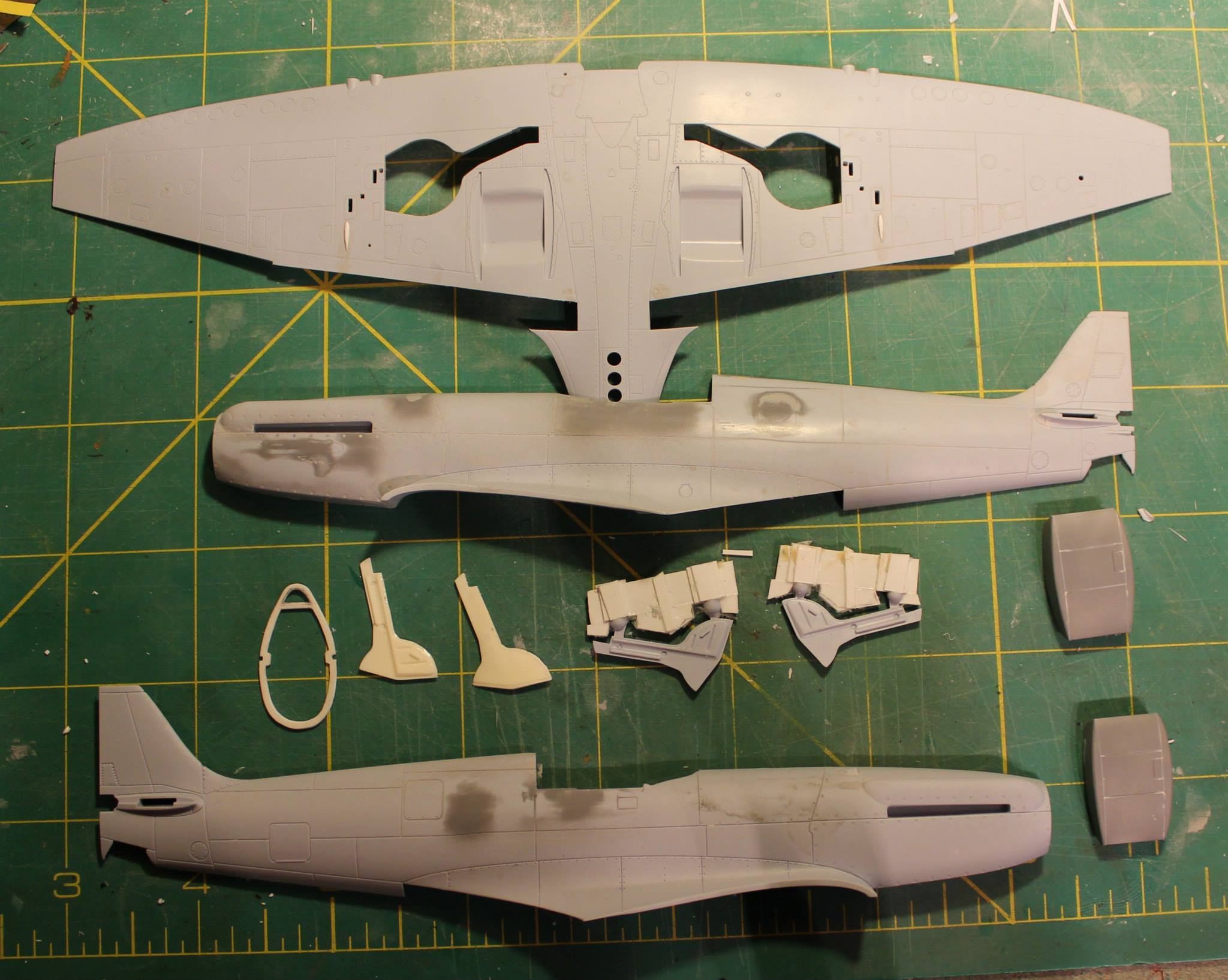
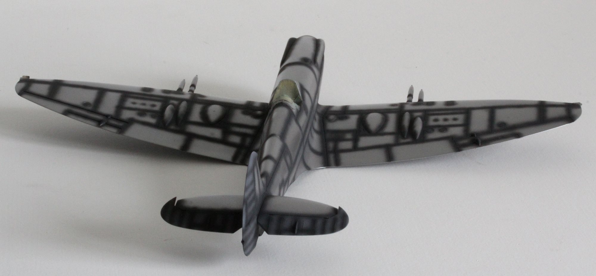
From these pics you can see I’ve already made some effort to change panel lines for the fuselage hatches and lopped off the crude triangle lumps from the top surfaces of the ’46 wings – they are supposed to be open flap mechanisms. Hmm.
Parts from donor Seafire 46/47 kit:
- Mk 46 wings; 3 pieces, two tops and the lower full span piece.
- Main flaps, items 60 and 61. Use the Mk XIX ‘down’ optional items for the smaller inboard flaps.
- Undercarriage doors and legs. Using these would leave the Seafire 47 airframe incomplete. This is unacceptable to me so I intend to clone them using my own casting methods (silicone rubber and 2-part resin; more details later).
- The long barrel 20mm cannon covers (or buy new ones).
- Seafire 46 windscreen.
- (With hindsight…) One might use the carburetor intake parts too.
Parts from elsewhere:
Required, from other sources other than the two kits:
- A gyro gunsight and mount. Mine will be scratch built.
- New decals, or I might make my own – undecided yet.
- New fuselage rear cockpit framing to replace the Mk XIX’s rear pressure bulkhead. Mine was scratch built.
- Whip aerial made from stretched sprue (or whatever you normally use).
- IFF di-pole aerial from stretched sprue.
- Wingtip navigation lights. Made from scrap clear sprue.
Optional (and obviously there are more possibilities here, such as some PE, for your own improvements):
- Since I like displaying my Spitfires with the cockpit door open I scavenged the spares box for a replacement standard Spitfire cockpit door suitable for and unpressurized airframe (from an ICM kit I think – a MkVII!).
- The XIX’s 5-bladed prop and spinner are good looking, more so than that of the 46’s, and would be the item of choice to use here. The ’46’s has a spinner about 0.5mm in diameter too big for the XIX fuselage and the blades have a very strong twist. The real Mk XIX prop measured 10 ft 4.5 in in diameter. The F.21 used an 11ft prop so I bought a new scaled 11ft diameter resin item to use instead of either XIX or ’46 kit parts (Barracuda Studios BCR48026).
- New long-barrel 20mm cannon covers from Quickboost (by Aires) QB48064. I could have made do with the kit items, leaving the short-barrel versions for the Seafire 47, but these replacements look better.
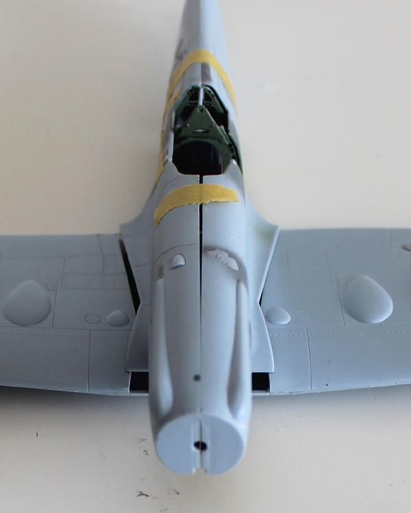
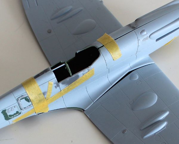
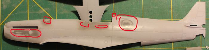
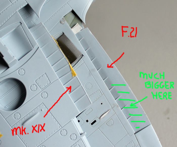
Fuselage skin modifications:
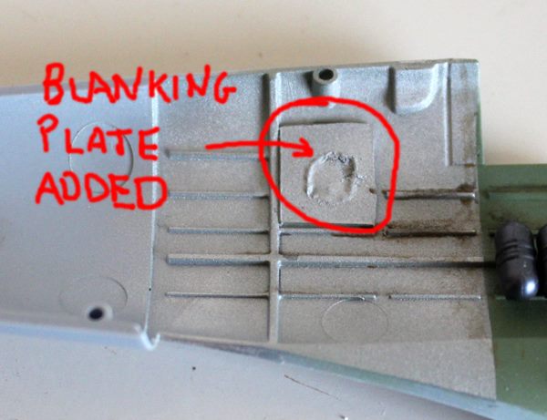
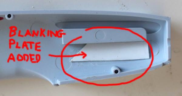
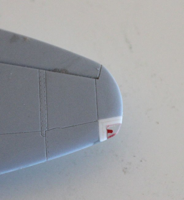
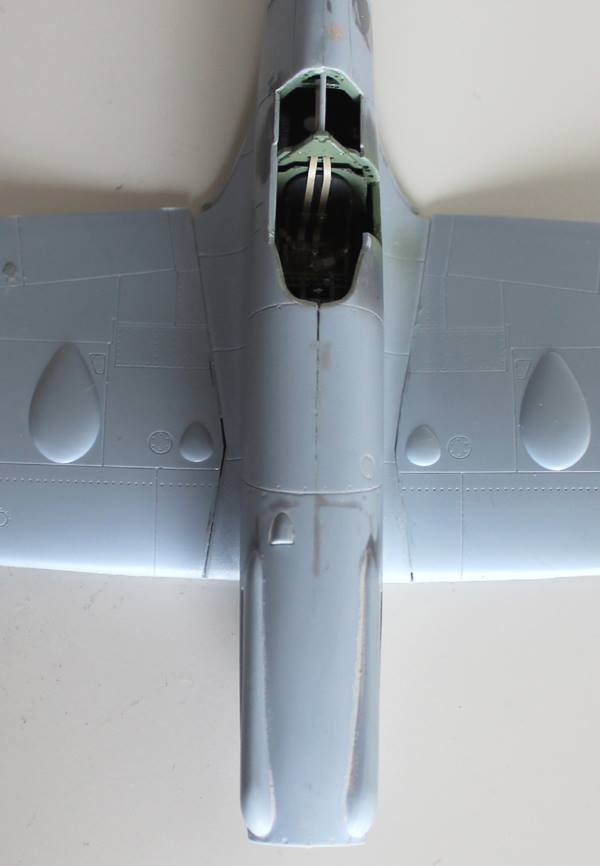
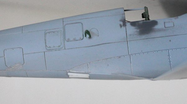
- Panel changes on fuselage; mainly filling camera-related doors. Both the port and standard camera doors on the XIX are to be filled, including the small D shaped door forward of the starboard camera hatch. A new access door was needed one door’s width aft and slightly below that filled on the starboard side. The pressurisation intake on the nose under the port engine exhaust and the exhaust outlet just behind the cockpit on the fuselage spine both need removing and filling too. In the photos below the red rings show where I am filling (including some sink holes around the cockpit and some mould marks just behind the cylinder head covers). The blue ring shows the rough position of the new hatch to be.

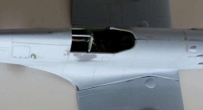
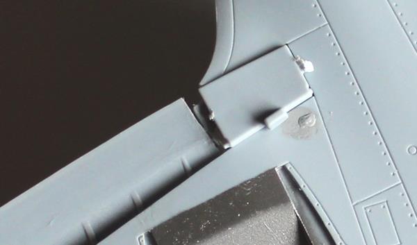
- Cockpit door. This is a mod since the late version Mk XIX kitted by Airfix has no side door panel lines moulded. It was easy to see where the door should be by taking note of the inner cockpit framing structure. Removing was a simply a matter of scoring and cutting. In the photo below the replacement ICM door was used to make sure the whole size was correct.
Wing skin modifications:
Just a couple of tweaks here.
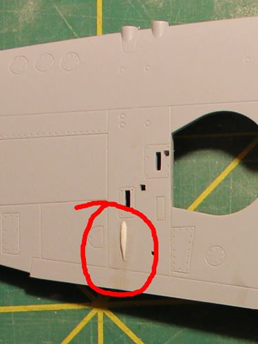
- Under wing cannon blisters. On the wing under-surface of each wing (on the kit ’46 wings), just aft of the shell case ejection chutes, is a blister shaped like a rounded rectangle. According to my limited references, these blisters should be slender and more pointed and tear-drop in shape. I removed the originals and added my own, shaped and sanded, from more plastic card.
- As mentioned in an earlier post above, there are two small triangular wedges on the both upper wing surfaces toward the rear and close in to the fuselage. There are the crudest representations of the flap mechanism which opens up proud of the wing surface when the flaps on the real machine are deployed. These had to go.
Moulding Replacement Items:
And this is ‘the big one’. If I couldn’t do this there was going to be no F.21 (there still might not be, but this was something I needed to prove out before I went any further).
As mentioned already, a number of the Airfix Seafire 46/47 parts are needed to complete the build. Since there are two sets of wings in the kit, a complete Seafire 47 is still possible but the F.21 needs a number of parts that are not duplicated, notably the undercarriage components. In order to provide these items for my F.21 I have moulded my own parts direct from the Seafire items.
Here’s how I did it.
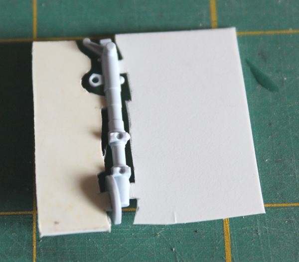
Creating The Mould:
- The first task is to mount the required part in a new ‘sprue’ to make a mouldable pattern (see pic of the oleo leg below, as an example). The part may be big enough not to need this, but I have found that doing this helps resin flow and air bubble reduction. My intent is to make a mould that is essentially a long slit that can be squeezed at the ends to open it up to allow the resin to fill it completely. And squeezing it flat will help push out trapped air pockets. To make a ‘slit’ I add flat plastic card to the sides of the part being moulded. Some thought is needed however. You need to think about which way up the part needs to be when pouring the resin; typically the bigger/thicker end needs to be at the top. As well as attaching the flat card I also build up some ridges that will become wider pour tubes in the mould. Here’s the trick; the plastic card is carved to closely follow the side contour of the part – a millimetre or less is ideal. I leave two ‘legs’ touching the part by which the flat card can be glued. When dry, the gap around the edge is filled with a dab of Kristal Klear which, due to capillary action, runs around the gap. Leave to dry and there’ll be a very thin film filling the gap. It’s important that there are no holes through the whole pattern otherwise it won’t come out of the mould.
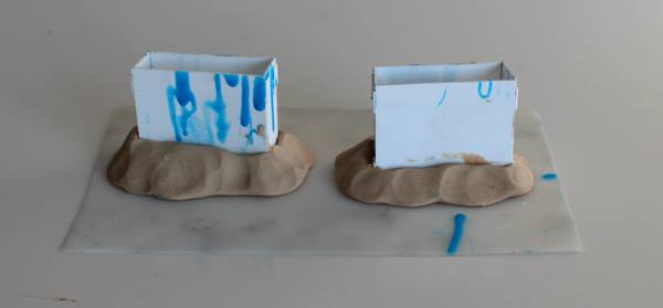
- Once the pattern is dry it is mounted on some modelling clay which is smoothed and blended with the pattern. The clay will form the top of the mould and the clay volume will be the resin mounting block from which the part will be cut.
- A plastic card ‘dam’ is built to fit around the pattern (see pics below).
- Before mixing and pouring, the inside of the dam and any modelling clay should be smoothed over with light gel-type grease (a branded product called ‘Vaseline’ is usually part of most women’s makeup kit! There are others). Cover the parts completely but keep the coat light.
- Before the dam is installed around the pattern, the silicone moulding compound is mixed. I then use an old brush to dab the silicone into the holes and detail of the pattern. This will help prevent air bubbles in the mould (which will create spheric lumps on the finished part).
- While still wet, the dam is installed around the pattern, and modelling clay seal is formed around the outside bottom edge of the dam.
- The silicone is poured carefully and slowly into the mould away from the pattern. The silicone should be allowed to flow around the pattern in its own time. The pattern should be covered completely by a good few millimetres of silicone.
- When dry, the solid silicone mould can be eased out of the dam, then the pattern can be eased out of the resultant mould.
- Once the pattern has been extracted the original part can be freed from the card – just like cutting it from an original sprue, The Kristal Klear should peel off. The part may need a little clear up before use, and a wash, but that’s a small price to pay.
- The mould then needs cleaning out i.e. make sure there’s no modelling clay left in.
- The fresh silicone has a tendency to gather and hold dust. Keep it away from your work bench – I store mine in little sealable plastic bags until ready for use.
Casting The Parts:
- With the silicone mould ready for use, the 2-part resin can be mixed according to the manufacture’s instructions. I use a very runny equal parts fast drying resin so I need to work quickly.
- Once well mixed I pour the mixture into the mould to about half or two-thirds full and then squeeze the mould repeatedly from both ends and sides. This squeezing seems to help the resin fluid around the walls of the mould and reduce air bubbles being trapped in the detailed cavities.
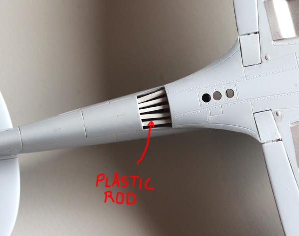
- The mould is then topped up with more mixture and set aside to dry – about half an hour or so. As an additional step with the F.21’s new oleo legs, I inserted a thin metal rod down the main leg void into the liquid resin. When dry this provided additional strength to the part – like making reenforced concrete.
- Making sure that the resin has hardened, peel back the mould from the part and gently prize it out.
- The new part, like the original and commercial resin parts, will require some clean up. You may find you need to make a couple before you get a good one. And you may find that your best one needs a bit of filler to fill in a couple of air bubble pockets.
- Wash the part before using it on the model.
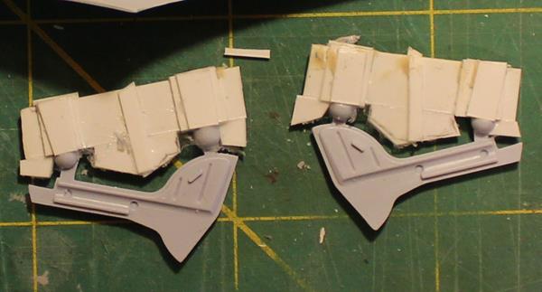
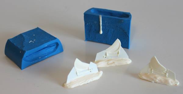
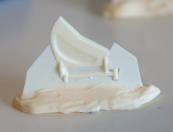
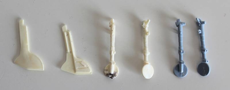
Here’s what I got for my efforts… (by the way, it took two attempts to get a good result with each oleo).
The light coloured parts are mine, the darker ones are the kit’s. The outer doors are also done.
(one of the legs needs a bit of repair due to my own inability to handle a sharp knife!)
Moulding Supplies:
There are plenty of moulding and casting suppliers out there. I used to following supplier and products:
MB Fibreglass:
- Polytek EasyFlo 60 Polyurethane Liquid Plastic Casting Resin
- Polycraft Food Grade Addition Cure Silicone Moulding Making Rubber
With hindsight I would use a slower drying resin next time.
Cockpit mods:
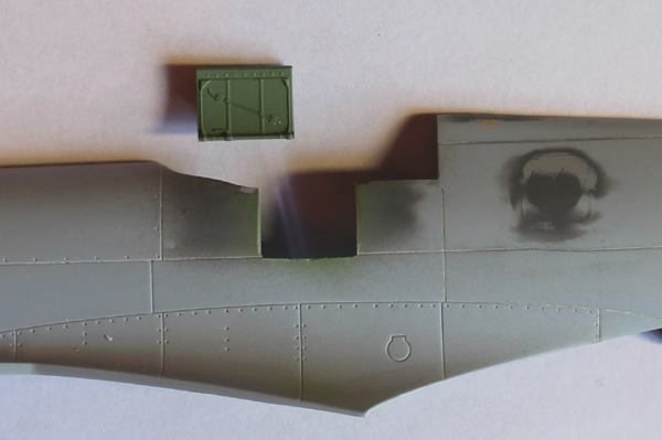
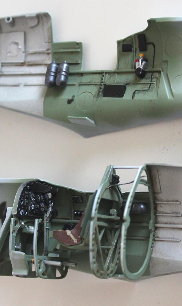
- The XIX kit comes equipped with cameras and fuselage structure to mount them. All this was omitted from the normal fuselage build, all the cameras and the three gas bottles right behind the seat – all added to the spares box ready for the Mk XI future build. However, I used the kit’s pressure bulkhead as a pattern for a non-pressurised version of fuselage framing. The picture below shows, on the right, my creation from plastic card:
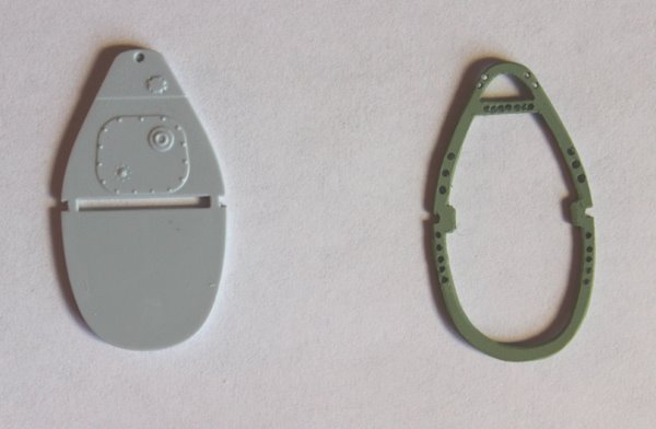
- As well as the bulkhead replacement I also removed the camera switch and control box from the cockpit instrument panel – it’s mounted where the gun sight should be. After clean up of the area I then added brackets for the gun sight (yet to be made) from more plastic card.
I’m not one for detailed scratch building of every detail in the cockpit. There are other builds that detail the addition of plumbing and other pipe work – I’ll leave that up to you. For me, I painted the available moulded detail and followed the XIX kit instructions for the rest of the cockpit build.
More on the cockpit later.
Markings:
Nothing like drooling over a nice clean fresh decal sheet to keep up the motivation through the boring build phase…
At the moment I am undecided; ocean grey/dark green or high speed silver with a polished metal cowling? At the moment I think it’s going to be Ocean Grey/Dark Green.
Here’s the front runner:
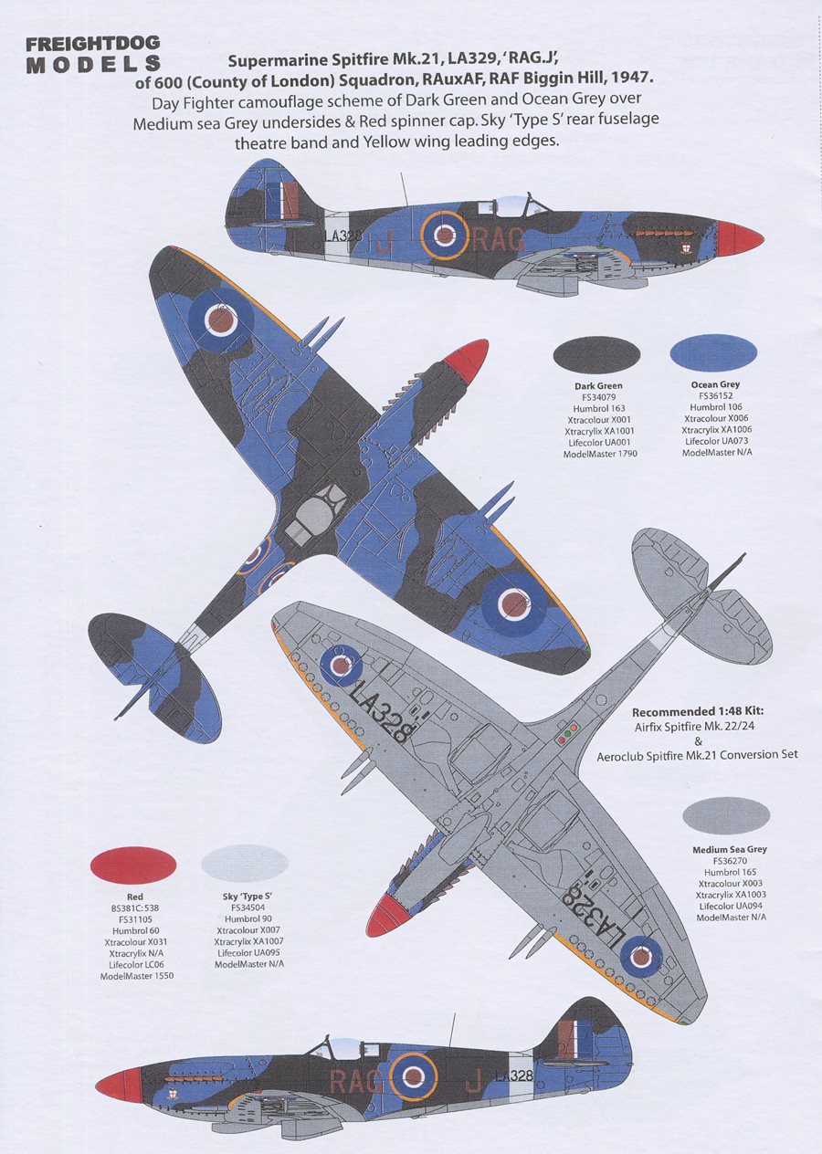
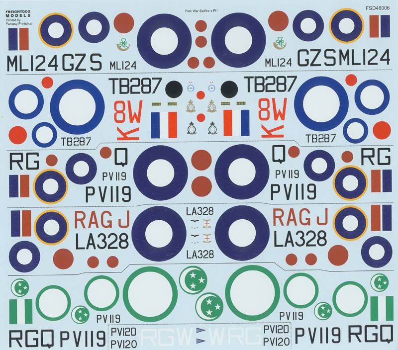
I just love Freightdog Model’s decals!
(Interesting that on this line art they have drawn in the beam approach aerial. I can’t find any photo evidence for this, yet)
Mating the Wings in Detail:
- I am glad to have confirmation that the horizontal tail is pretty much standard rather than a ‘Spiteful’ size as some 3-views would indicate. Obviously, this would of made a big difference to the look.
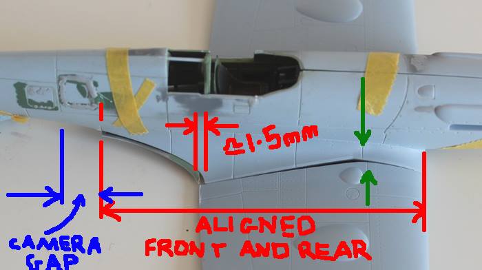
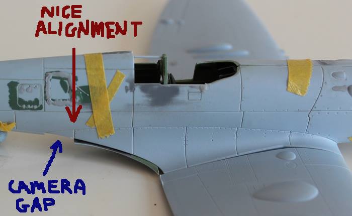
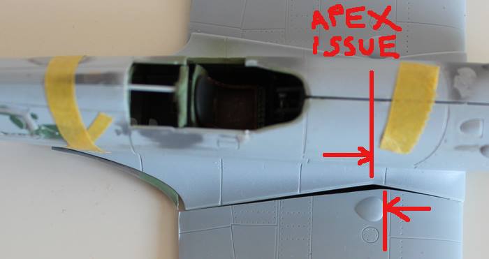
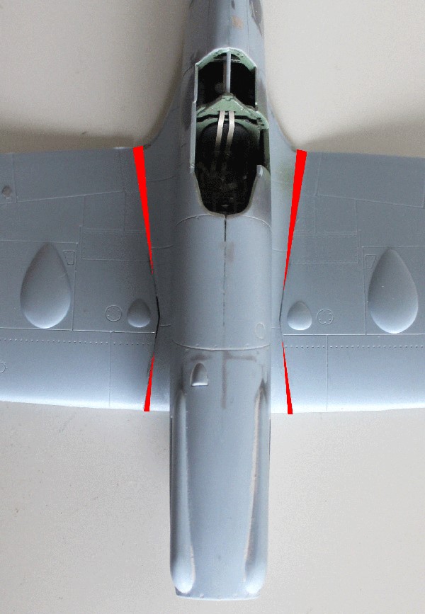
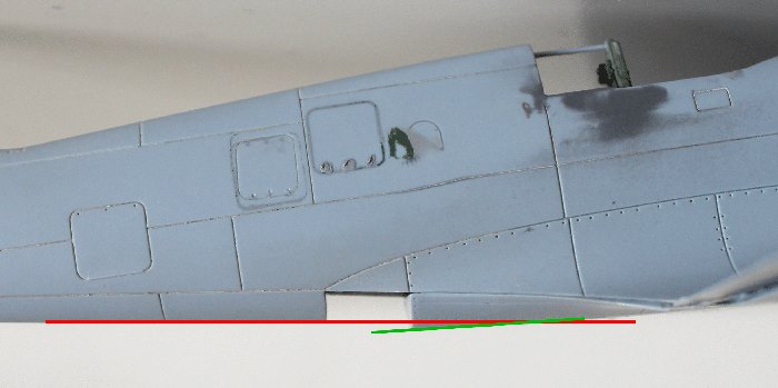
- On the wing-fuselage mating; here’s a couple more shots from a different angle, see below. Having just spent a few more minutes playing with this, I am still of the view that lining up the leading edge is the way to go. If I do this I think a make things much easier; around the carburettor intake and under nose panel, and at the trailing edge and rear wing root intersection. The only chore will be the main wing root joint – and I’ve seen kits with worse issues than this. Also, at the very rear, surprisingly, the very back edge of the ’46 lower wing part, where it joins to the fuselage (where the camera ports should be) does line up with the XIX panel lines. There is still the camera port gap to fill, but obviously that was always going to be a job to do anyway. (In the images, I’ve dropped the fuselage down into position without any side-to-side trimming. This means that more of the underside fillet is visible than will actually be there for trimming – i.e. the whole fuselage, in the images, has yet to be moved about 1mm to starboard. The narrowness of the XIX is a factor still in that the ’46 rear section mating under the fueslage is a tad wider.)
Here’s the photos…Blue shows the gap to be filled due to the loss of camera ports. Red is general wing alignment. The Green and ‘Apex Issues’ shows the ‘miss-alignment’ of panel lines associated with the main spar – although who knows if the panel lines equate to spar front edge or rear edge or centre line, or is this inaccuracies in the kits. Regardless, at the moment, I plan to live with it (or I may just fill and re-scribe the panel line on the fuselage, under the upper green arrow).
All good fun!
Undercarriage Doors:
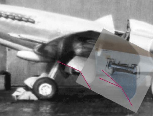
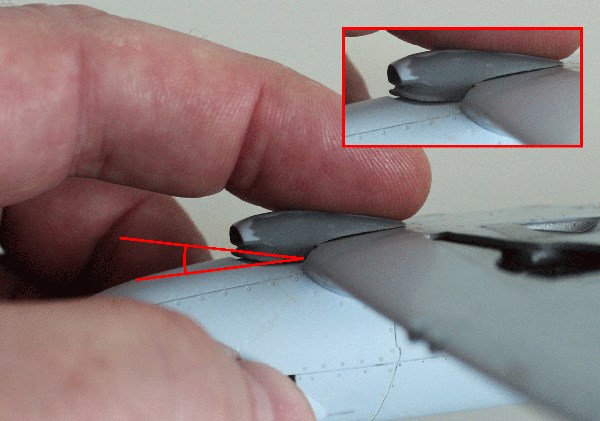
Just had a look at undercart doors… Bob, you are right, there are differences. From my photos it looks like 21s had a set of doors with less of an angle on the leading side – more likely to foul an arrestor wire I guess. Seafire 46s and 47s seem to have a steep leading angle on the main U/C door. But… I have a couple of pics of 21s with the same 46/47 type door (notably LA139). But there’s another ‘but’… the kit parts from the 46/47 seem to reflect the angles on the majority of 21s! Go figure! Was there are mod retrofitted back onto some 21 after the improvement for Seafires? Not looked at the Seafire 45 yet. I have pics of Mk 22s with the same steep angle as the Seafire. Here’s a pic to show the extent of the difference:
- First pic is a Seafire 46. One can see the steep leading angle on the main wheel door.
- The second pic shows, not very well (I have better photos in a book) a Spitfire 21.
- The third pic shows another Seafire and overlaid is a scrap of the outer kit door. It is real clear to see that the kit door follows the F21 angles! I have a photo of an F21 underside onto which I can physically lay the kit parts. This backs up the fact that the kit parts are better shaped for a F.21 than they are for a Seafire!
The more one looks, the more one sees. Looking again I see other photos of 22s and 24s with a mix of different UC door types. There’s a photo of 24s under construction at South Marston with the non-Seafire type doors, yet there are photos of late 24s with the Seafire-type fitted (VN324 for example). I’ve now seen 24s with the Royal Hong Kong AF with both types fitted – in the same squadron (VN318 and VN485).
I assume Airfix must have kitted up their Spitfire 22/24 first and just reused components for the Seafire 46/47, not noticing that the UC doors on the earlier 22s and 24s are different to Seafires. And these Seafire doors must be a dead swap (in matched sets) for the earlier type and retro fitted at MUs or on squadron, or something like.
Looks like I should just use the Seafire 46/47 undercart parts for my F.21 and think about building some correctly shaped parts from scratch for my Seafire 47 later! That moulding my own replacements to save the 47 was a waste of time.
Seems like we need some resin improved replacements for the 46/47 kit.
Researching is the best bit about modelling, well, almost!
Radiator Tubs:
Again, it’s my plan to leave the Seafire 46/47 kit with a completely buildable Mk 47. To this end I plan to use the radiator tubs from the Mk XIX. But these are a different shape to those of the Mk 21, and they join to the under-wing surfaces with a slightly different joint line.
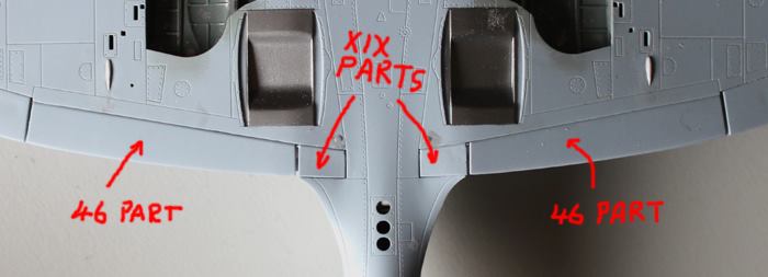
Here’s a pic of the Mk XIX and Seafire wings, viewing the underside centre section:
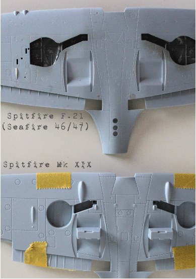
The Mk XIX kit is the better thought out. The joins for the rad tubs fall on the panel line, while those of the Seafire do not – part of the rad tub edge is moulded onto the wing underside.
This means that adjusting the Mk XIX rad tubs to fit required 3 stages.
- The first stage is to trim the edges of the rad tub until they fit into the curved slots of the Seafire wing.
- Second stage is to build up the edges of the rad tubs as those of the F.21 look wider/fatter than those provided with the Mk XIX kit.
- The last stage is to trim back the rear profile – cutting an angle in from the bottom of the tub up to the wing under surface.
Here’s a few pics of what’s going on:
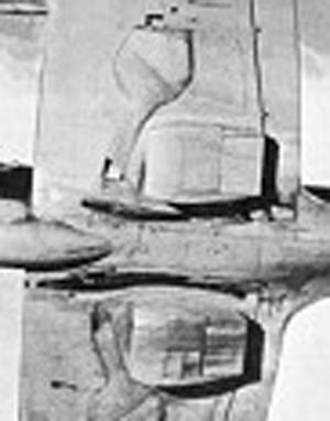
This picture is Spitfire F Mk 21 underside showing the shape of radiator tubs; right.
Diagram [1] below shows the contours of both Mk XIX and F.21. The Red lines are those of the Mk XIX kit – the outer set are the join lines into the wing slots, the inner lines are the contours of the tub wall. The Green lines show the new contour needed to fit the Seafire undersides – which is fatter and rounder than those of the XIX.
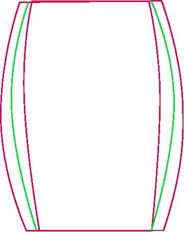
Diagram [2] shows what material was removed.
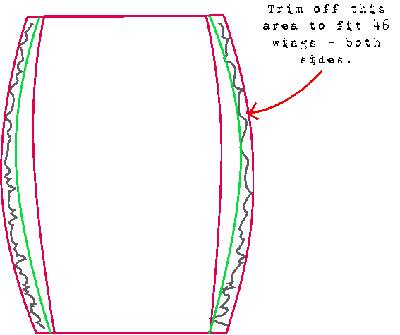
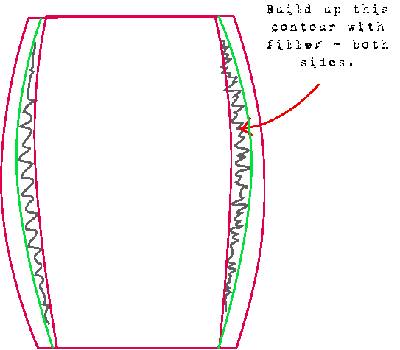
Diagram [3] shows what material (filler) was added then sanded back in order to create the right shape.
And lastly, the picture below shows the ‘before’ and ‘after’.
This image also shows the area on each side that I chopped off in order to get the correct looking profile, and to fit the Seafire wing slots (shown by the little red triangle).The final picture shows a good close-up shot of LA188. You can see the shape of the radiator tub rear in this:
While I was at it, I also closed the radiator shutters, just for something different. The finished item on the right has a coat of primer (to spot issues with the filler) and panel lines re-scribed.
Both are sides are done and ready to attach. When the time comes, I will be using the XIX kit parts for the internals – the radiators.
References:
Following on with the F.21 undercart doors observations here’s the main references I’m using:
Books:
A – The Spitfire Story, by Alfred Price
B – Spitfire, A Complete Fighting History, by Alfred Price
C – Camouflage & Markings No1 RAF Fighters 1945-1950 UK Based (Scale Aircraft Monographs) by Paul Lucas.
D – Camouflage & Markings No5 RAF Fighters 1945-1950 Overseas Based (Scale Aircraft Monographs) by Paul Lucas.
The internet:
Here’s a list of some of the photo evidence I’ve seen on this subject (obviously this is a limited list since it’s only photos where the doors can be seen):
Mk 21s, 22s and 24s with ‘Spitfire’ doors:
- LA187 (B, page 243). I can’t confirm the serial from the photo however. If it is LA187 the she was repaired and upgraded, see below.
- LA188 (B, page 247) (A, page228)
- DP851 and PP139 prototypes (B, page 242)
- 21s under construction at South Marston (B, page 244/5)
- LA217 with contra-prop (Internet)
- LA255(?) (couple of photos; colour photo: Internet)
- In service 91 squadron machines, DL-F and DL-Y (A, page 230)
- LA218 (A, page 231)
- LA232 (couple of photos in different paint schemes: Internet)
- LA256 painted in silver with post war bright red/white/blue markings. (Internet)
- LA331 also painted in silver with post war bright red/white/blue markings. (Internet)
- LA228 painted siliver, polished cowel, RAuxAF (C, page 51)
- LA308 RAuxAF (C, page 26)
- LA275 RAuxAF (C, page 26)
- LA223 RAuxAF (C, page 22)
- LA315 41 Sqdn (C, page 10)
- LA276 1 Sqdn (C, page 3)
- Mk 22 PK683 (Internet)
- Mk 22 PK605 (C, page 79)
- Mk 22 PK437 (C, page 79)
- Mk 22 PK562 (C, page 53)
- Mk 22 PK430 (C, page 31)
- Mk 22 PK569 (C, page 69)
- Mk 22 PK481 (Internet)
- Mk 22 PK431 (Internet)
- Mk 22 PK542 painted in silver with post war bright red/white/blue markings. (Internet)
- Mk 22 PK599 (Airliners.net: Internet)
- Mk 24 VN485 (Internet)
- Mk 24 PK724 as she is in Hendon. Difficult to count museum airframes as they may have been cobbled together from parts that fit. (My own photo collection)
- Mk 24 PK713 (Internet)
- Mk 22 prototype PK312 (Internet and A, page 232)
- Mk 22 PK547 (Internet)
- Mk 24 or 22(?) PK684, or it might be 664 or 634, contra-prop (Internet)
- Mk 24 VN318 80 Sqdn (D, page 83)
- MK 22 PK690 74 Sqdn (D, page 35)
Spitfires with ‘Seafire’ doors:
- F.21 LA187 as photographed by Air Service Training, a repair organisation. The photo is entitled ‘Last of the many’ and implies the subject is the last repaired airframe dated Dec 1946. She clearly has ‘Seafire’ doors at this point. (Internet)
- F.21 LA198 shown in post war bright red/white/blue markings (b/w photo). A little difficult to see, but looks like Seafire doors. (Internet: Air Britain Photographic Images Collection). And F.21 LA198 as she is hanging in the museum in Glasgow (assuming it’s the same airframe).
- VN324. Billed as “a late production Mark 24” (A, page 237)
- VN318 ‘E’ RHKAuxAF, ex- 80 Squadron airframe I think. (A, page 238), And on the opposite page is VN485 with ‘Spitfire’ doors – and these two pictures are implied taken at the same time for the same event in 1955 and thus imply mixed use on squadron.
- F.21 LA269 LO-(?) with guns removed. Photo looks late, post ops. (Internet)
- F.21 LA139 painted silver with post war bright red/white/blue markings and guns removed. (Internet) […Bad info, I miss read the serial on a poor black and white photo of LA198. There is no LA139! Sorry.]
- Mk 24 VN496 TN- (Internet)
- Mk 22 PK481 modern photo of a museum airframe so it’s difficult to count this one. (RAAFA Museum: Internet)
- Mk 22 in Egyptian service in several photos (Internet)
- Mk 24 VN318 with Seafire-like bullet/torpedo shaped centre line drop tank and wing mounted bombs. (Internet)
- Mk 24 VN317 with 80 Sqdn (D, page 16)
All the pictures I have seen of Seafires, including some of Mks XV and XVII, all show ‘Seafire’ style doors. The Airfix 1/48 Seafire XVII has correctly shaped doors.
I have pictures of TM379, the Seafire 45 prototype, and she’s clearly booted with ‘Seafire’ type doors for sure – and looks very different from the clear photo of LA139 looking very obviously a 21 without a hook.
My conclusion from all this:
- F.21s with the ‘Seafire’ doors seem to be very late, or even post operational career, and are fewer in number judging only by the proportional split on the photos I’ve seen – and where the doors are visible. Most F.21s have the ‘Spitfire’ doors, with limited arrestor wire clearance. This seems true for Mks 22 and 24, although more care is needed since there’s a greater chance Seafire-type doors might have been fitted.
- The doors, as moulded for the 46/47 by Airfix, with the low leading angle forward of the wheel axle, are not correct for the 46 or 47 airframes. They are, however, correct for a percentage of Mks 21, 22 and 24 airframes – but due to some retro fit or late production mod, one should try and check 22s and 24s with direct photo evidence.
I plan to use my cloned Airfix doors, unaltered, for my F.21. My Seafire 47, when I get to it, will need a change of doors, somehow.
This all means that when building a Spitfire F.21 from the two Airfix kits (the whole point here), depending on how accurate you want your remaining Seafire to be, you could go ahead and just use the doors on the F.21 – without all the trouble of cloning (like wot I did) – and accept that you will need to source better ones for the 47 from elsewhere.
Navigation Lights
Time to get back and do some real modelling…
I’ve included little section here on the navigation lights because to build the F.21 and still save the Seafire 47 one needs two sets of navigation lights. The Seafire 46/47 kit parts will remain with the Seafire, and I will scratch build new ones for the F.21.
This is simple stuff, and I know many of you do this already, but for completeness, and for anyone else, here’s what I did:
- With the wing top and bottom halves mated, I cut some strips of plastic card to make packing/filler pieces. The kits parts include moulded-in part of the wing structure. As navigation lenses they would be too big. This means that the slot in the ends of the wings are too big to be completely filled with navigation light lens. This is not a big problem, I could have just over painted the extra area. But I couldn’t find any large enough clear plastic or sprue. So I added to layers of plastic card into the navigation light slots and left to dry.
- I found the thickest bit of clear sprue I had. After trimming off the end, I held the end high over a candle and allowed the sprue to soften – this is a bit like glass blowing. It’s can’t be too hot or it will become too runny or even burn; just so it starts to droop under its own weight, seemed enough.
- With the sprue ‘soft’ I pushed the softened end into the navigation light slot. This caused it to ‘bunch up’ into a larger blob. When I thought I had enough I blew on it to cool it.
- Once cool, in a few seconds, I pulled it clear of the slot.
- I then drilled a small hole on the inside flat surface and filled the hole with a dab of red paint for the left/port light and green for the right/starboard one. These, hopefully, will look like little bulbs inside the lens.
- The shaped ‘blob’ was cut from the end of the sprue and super-glued in place on the wing.
- Once dry, the packing, and ‘blob’ lens were sanded back to shape and then polished to regain some shine.
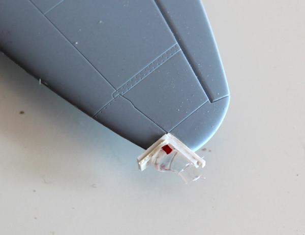
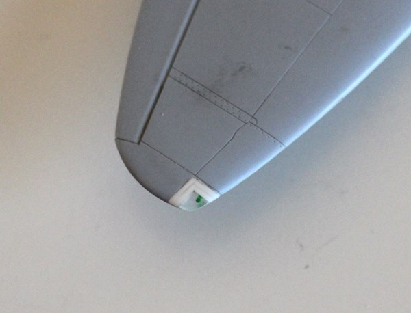
These will be masked with masking fluid during painting, but will also receive a coat of clear red and green gloss toward the end of the build.
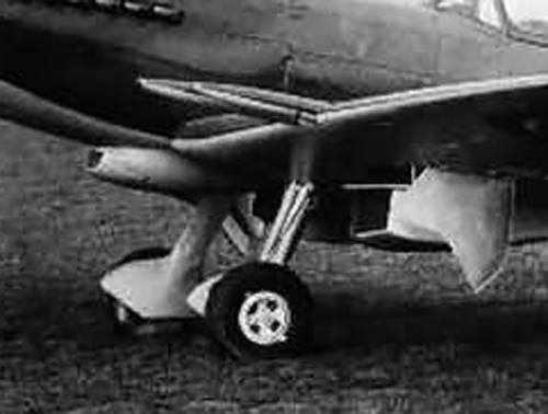
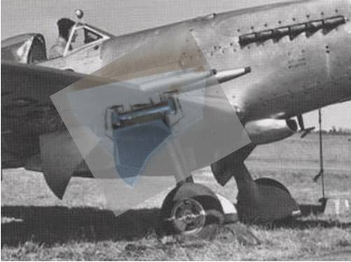
Slipper tank hooks remains a bit of a mystery for the F Mk 21 then. My limited sources of photos only yields two photos on which I can see anything like a hook, and I have already posted one when talking about U/C geometry. Here it is again:

The other is in The Spitfire Story, Alfred Price, on page 228. Looking at the underside shot of the 2nd production airframe I think I can see the shadows of the hooks in amongst the oil staining. But this is not crystal clear by any means.
So at the moment I’m not sure what I’m going to do about this. I want to think that since these tanks seem to have been used to some degree by RAuxAF squardons operating Mk 22s, I want to think that it would be the same for Mk 21s. But that’s just guessing. I’ll probably leave them off. If they were commonly present I’m sure I’d of seen more than one example by now. Despite the provision for them, they seem not to have been used much on the 21.
More on Cockpit mods:
I’m now at the point of closing up the fuselage – and then I can tackle the big one; getting the fuselage and wings joined.
Anyway, here’s a few shots just before I glue the fuselage halves together.
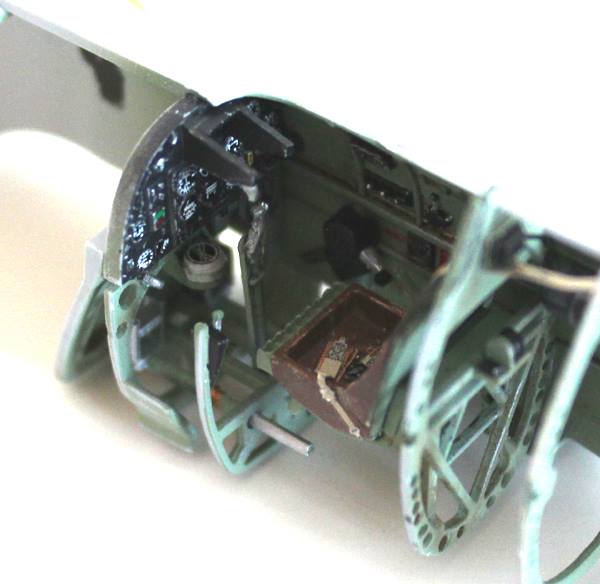
You’ll be disappointed here, I’ve not applied the same passion for detailed accuracy to the inside as I’m striving for on the outside. I don’t have the patience or skill for such detail. As you can see, the inside is basic for a 1/48th scale Spit. Most of what you see is standard with the Mk XIX kit. The differences are:
- Rear pressure bulkhead (part no C8) is not fitted. A scratch replacement is fitted instead – the F.21 was not pressurised.
- The structures supporting gas tanks and the canopy spring emergency release do-dad is all omitted (kit parts C10x3, B19, B12, D3).
- The whole rear camera bay contents is also left out (parts C2, B10, C20/21, C22/23, A13, C9).
- I chopped off the basic blocks that represent the rudder pedals and scratch-built my own.
- I hate the thick, slab of plastic that represents the armour plate, so this got replaced with a thinner sheet of plastic card (using the original as a template).
- I added the gas tanks from the XIX kit into more ‘normal’ Spitfire positions – I know this isn’t that accurate, purists would want to do better.
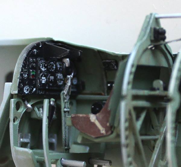
- The instrument panel was modded by removing the camera control box and replacing with a scratch built gyro gunsight holder (I’ve yet to make the gunsight). This is an important ‘XIX to F.21 mod’ as it will be very visible through the cockpit hood.
- Just behing the seat frame, I added a couple of extra bits of scratch built details to pad things out. I think these represent the voltage regulator and an altitude sensor/switch thing. Again, this isn’t totally accurate stuff for an F.21.
- Eduard seats belts, as always, have been added. These are the late type with the central quick-release box fastening rather than the earlier ‘pin’. (This is a whole subject all to itself).
And that’ll be that. Later today I’ll stick it together and then, perhaps tomorrow, I’m on for the wing-fuselage joint.
Airscrew:
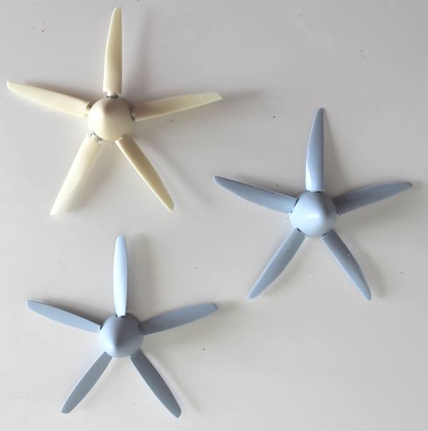
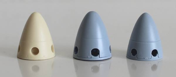
I have a choice of 3 airscrews and spinners for this build. The first is from the Mk XIX kit, the second from the Seafire 46 and the third being a resin replacement from Barracuda.
There’s a clear winner in terms of quality, shape and surface; the Barracuda example. But it’s too big. The spinner and backplate, moulded as one, is clearly a lot bigger than the Mk XIX fuselage.
I measured all three spinners as best I could. The ’46’ and Barracuda come to just about 15-1/2mm. The XIX is about 14-1/2mm.
Shape-wise, the Barracuda and XIX are similar, apart from the XIX being smaller. The shape of 46 is quite ‘bulbous’.
The blades length of each measure; 25-1/4mm for the XIX, 27-1/4mm for the ’46’ and a tad less than 27-1/2mm for the Barracuda’s (measured down the centre-line of each).
Since the F.21 used a bigger diameter airscrew from the XIX, and since both ’46’ and Barracuda spinners are too big, I plan to use the Mk XIX spinner mounting the Barracuda resin blades.
If you didn’t have the Barracuda option then I guess, to get the bigger diameter prop, you could use the ’46’ blades with the XIX spinner. But I do agree with others, the ’46’ blades are not that nice; shape-wise and they have a pronounced twist.
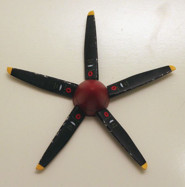
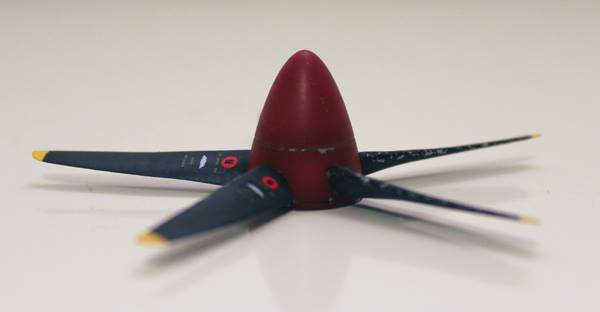
Airscrew:
Got fed up with sanding and filling and more sanding, so I painted the prop. As described above, this is the Airfix XIX spinner with the Barracuda resin blades.
The last photo shows this hybrid next to a finished Airfix Mk XIX for comparison.
Paint Process:
Blades:
- Warhammer Chaos White rattle can primer.
- Thinned and sprayed Humbrol 154 acrylic yellow tips.
- Mask tips with tape; measured to 2mm (approx 4in in 1/48).
- Sprayed main colour coat of Tamiya Rubber Black XF-85.
- Masked blades with tape to leave a thin leading edge approx 1/2mm.
- Spray leading edge Tamiya Black X-1.
- Chip leading edge with Humbrol Aluminium 27002.
- Removed all masking tape.
- Washed with extremely thin light grey mix of oils onto matt Rubber Black surface. Dab off excess with tissue.
- Sealed with thinned Johnson’s Klear.
- Applied decals – I used the same ones from the Mk XIX kit – using Microscale’s Micro Sol.
- Sealed decals with Klear.
- Final coat of thinned Microscale’s Flat.
Spinner:
- Primed with Alclad 2 Dark Aluminium.
- Sealed with thinned coat of Johnson’s Klear.
- Applied very small dabs of masking fluid in areas to show up as paint chips.
- Pre-shaded around holes and panel lines with Tamiya Rubber Black.
- Applied first thinned, light and even coat of Tamiya Red XF-7.
- Applied highlighting between blade holes and around the end if the spinner with thinned Red+White mix.
- Added another light coat of Red colour to balance things up.
- With water and stiff brush I removed masking to reveal Alclad chipping.
- Sealed with Klear.
- Gave the whole thing a light polishing with very fine wet and dry polishing cloths.
- Applied a final Microscale Flat coat.
(The Spitfire Mk XIX in the above photo, by the way, is in the RFI section; here)
Wing Attachment:
So the joint is now dry, the wings are on, and it was fairly straightforward…
- The first job was to carve the upper surfaces of the wings to remove triangular-shaped wedges from in front and behind the main spar position as the wing fillet on the XIX is wider than the 46’s.
- I used super-glue to attach the wing rather like using a welding touch to tack-weld a part in place before the main weld; I glued the rear under-fuselage spur of the wing centre-section on to the XIX fuselage, making sure everything was aligned side-to-side and, as planned earlier, I aligned leading edges as my main datum front-to-back.
- Once dry, I tack-glued the front leading edge either side of the carburetor intake.
- The next bit was tricky. I used liquid-poly cement to attached the wings at the wing root join. The tricky bit was making sure the wing upper surfaces were flush with the wing fillets on the fuselage leaving no harsh ‘step’. To help this, at the trailing edge under-side, I added some wedges of plastic card.
That’s about it.
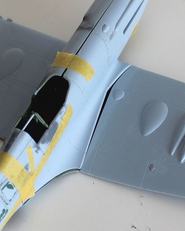
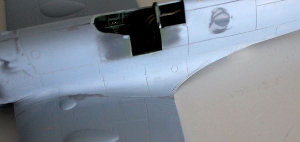
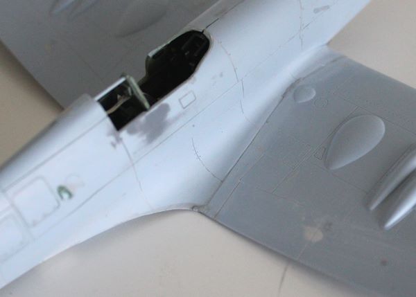
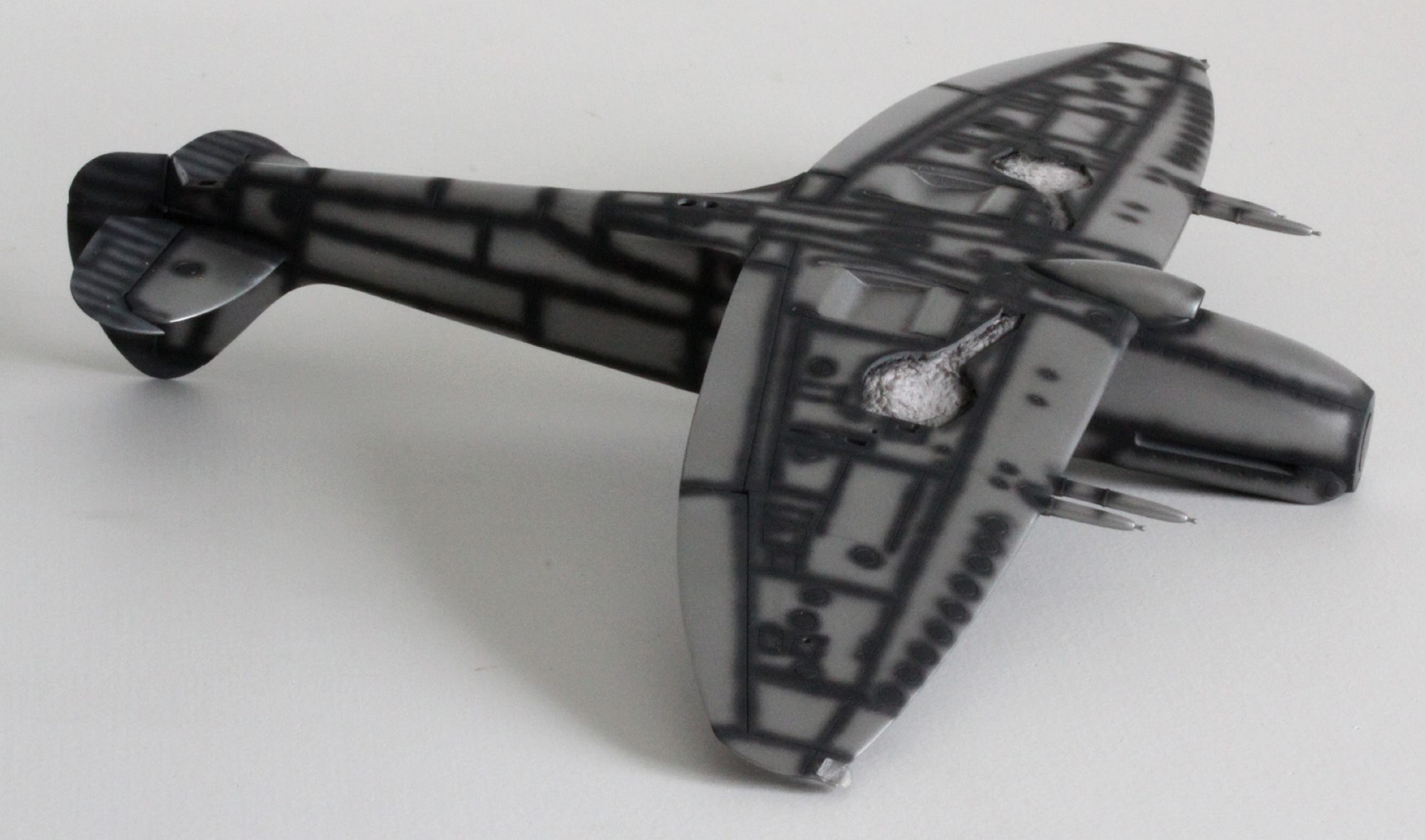
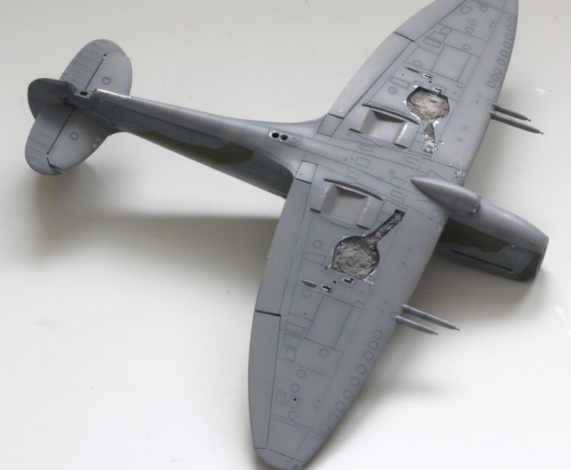
Here are some photos before I start filling and sanding (I hate filling and sanding!)…
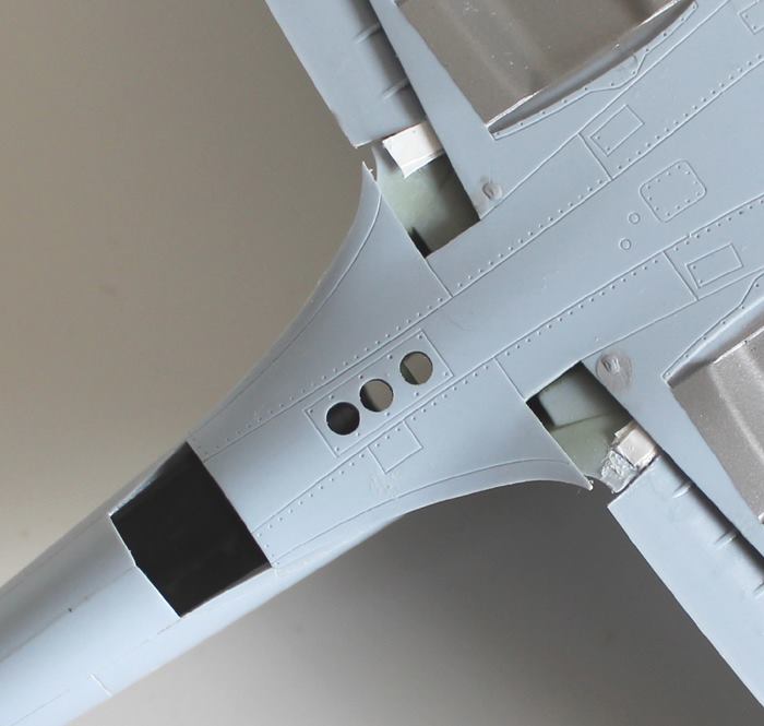
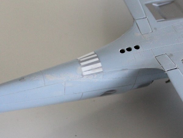
The massive gap shown in the underside view is from where the camera ports would be on the Mk XIX. This will be filled with plastic card and filler. This shot also shows the slipper tank hook attachment holes being filled and the three signal lamps which I plan to fill with Kristal Klear or clear 2-part epoxy.
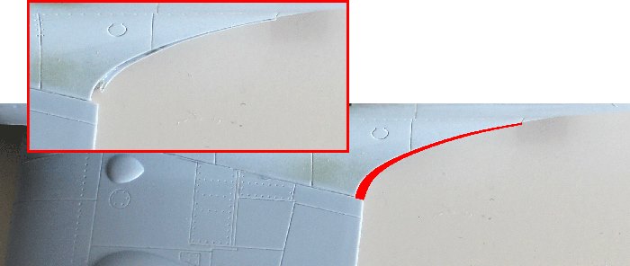
A close up of the wing root. You can see that the ’46’ wing is about 1.5mm bigger in chord than the Mk XIX’s fillet. The Red area shows what must be filled and blended. The 46’s fuselage fillet contribution underneath is about 1/3mm wider on both sides. This actually helped me align the joint.
And an unexpected issue; the rear fuselage profile of the two parts does not align. Yet more sanding will be needed here!
And a second unexpected issue; some work will be need to get the carburetor intake to fit. I think this will require some curving-off of the leading edge or the intake.
Just a quick note on attaching all the horizontal surfaces:
As a rule, I tend to attach the main wings of a Spitfire to the fuselage first, before the tailplane. Most kits are the same with a single underside for both wings and separate upper surfaces. This means that any correction to dihedral may require bending of the under surface part at the root, and possibly some carving. In attaching the wing I will sight down the fuselage to the fin and try and achieve an equal dihedral angle on both wings relative to the fin. But once dry, and despite binding, this equality isn’t always there.
Then I attach the horizontal tailplane sighting alignment onto the main wings – not the fin. This might mean the fin, if there is a main plane dihedral issue, look like it is at a very slight angle to the tailplane.
Since the undercart attaches the main wings, tending to level the airframe relative to the wings not matter what’s going on with the fuselage, once on its wheels, using this method ensures all wing surfaces are level to the ground and only the fin might be a little off the perpendicular. Since the fin is the smallest of all flat surfaces, the miss-alignment is far less noticeable.
If one attaches the horizontal tail before the main wings, and there is a slight error in wing dihedral, the result will be a more noticeable ‘twist’ in the fuselage which will be exaggerated by the tailplane noticeably not level to the ground.
Pause in the Build:
A-ha!! Look what the postie just delivered… updated and reprinted…
There’ll now be a brief pause in the build while I re-check my plans against this new source of info!
More on Flaps:
The flaps will be ‘up’. It’s quite rare to find a Spitfire with its flaps down on the ground and parked up. The crude ‘wedges’ moulded on the upper surface, that represented the flap mechanism when ‘down’, has already been shaved off. I’ll be boxing in the holes and adding some support before I lay in the flap items flush with the underneath. You’re right, the added material will be useful for supporting the required filler to bland in the fillet on the upper surface.
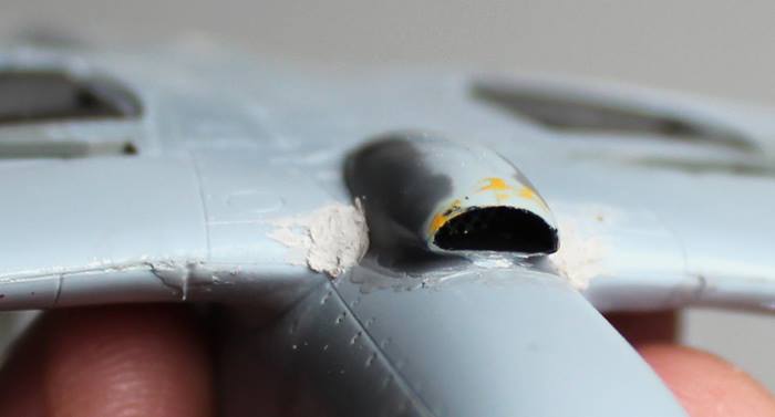
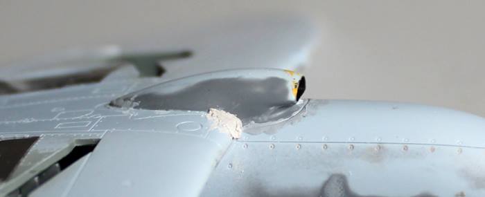
Carburetor Intake:
The prepared Mk XIX intake is a poor fit now that the wings are attached – see earlier post. Here’s the Seafire 46 intake held in place for a test fit:
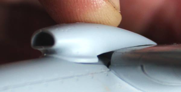
The fit is ‘different’. I’m not sure if it fits better, or not.
The intake touches front and back but leaves a larger gap in the middle. Of more concern is that the Mk XIX fuselage curves away quicker than the intake’s moulded-on fuselage section resulting in a large lump sticking out on either side.
I think my options are:
- Use the XIX’s and cut away the middle area. I think this would reduce the depth of the intake in side profile, and making it look flatter against the fuselage underside.
- Use the 46’s, cutting away the sides and adding lots of filler. This may result in a deeper profile – and loads more tricky filling and sanding !!
- I think I could use a bit of both, making a horizontal cut and using the best of both.
At the minute, I think using the 46’s is the best option, but I may fill the wing area and get the leading edge curve sorted before adding the intake.
I think a closer look at some photos and drawings in this area is in order before I finally decide.
Flaps:
Forgot about the flaps.
I will be displaying the model with the flaps up. It is very rare to see a Spitfire with the flaps down while parked and displaying them down requires the scratch building of the hinge mechanism and door that pokes through the wing upper surface. And I am not doing that here. This means I can use the flaps, when added, as additional support for filling the gaps on the upper wing surface around the root trailing edge. But… I need flaps from some place.
The 46 wing has very much bigger flaps than the XIX. Newer Airfix 1/48 Spitfire kits tend to have 2 sets of flaps, for display ‘up’ or ‘down’, but not so the 46/47 kit. However, since I am robbing the 46 and leaving a buildable 47 I will in deed take the main flaps from the 46 kit. The Seafire 46 and 47, in the Airfix kit, do share the small inboard flaps so stealing these would leave me short for the 47. These are parts 62 and 63. Luckily, the hole in the wing of the 46 takes the Mk XIX kit part – and the Mk XIX kit has 2 sets which will still leave me with a complete set of wings – and flaps – for my future Mk XI ! Bargin!
So I will use parts 60 and 61 from the 46/47 kit, and parts B21 and B22 from the Mk XIX. B21 and B22 are the items for displaying the flaps ‘down’ so will need the little attachment tabs nipping off.
Flap Operation:
I read from the Spitfire V Manual from Arms And Armour Press that the flaps are operated by compressed air to force the flaps down into the on-coming air. But selecting ‘up’ doesn’t operate the compressed air system, instead the flaps are raised by the combination of slip-stream and a spring. So once parked up with engine switched off there would be no slip-stream to raise the flap leaving it available for spiders, nesting birds and other invasions of crud. So no wonder common practice was to raise the flaps as soon as you were down on the ground. I don’t know if this system continued throughout later marks.
Flaps:
Done.
Some very minor trimming needed to get the small inboard flaps to fit snug.
Camera Port Gap:
Filling has started…
Basic stuff. Probably more ways to sort this. Once dry I’ll slap some putty on that structure.
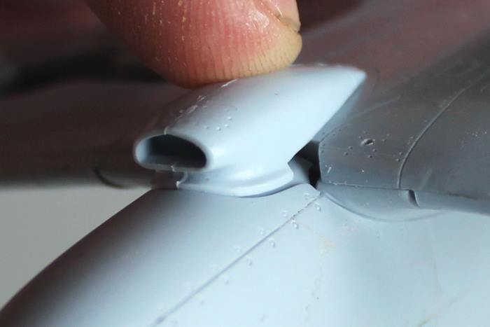
Carburetor Intake:
’46’ or ‘XIX’? I chose to use the Mk XIX’s intake and it proved to be a snap to fit with only minor shaving to get it to bed down nicely.
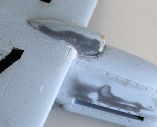
The nasty holes either side have been plugged with filler and the whole seam dabbed with Mr Surface. It’s an awkward area of the airframe with some interesting intersections of different curves. Sanding will be tricky; but that’s a Spitfire for you!
Despite the level of detail reported here, this has been a fairly easy conversion so far and, touch wood, most of the ‘difficult’ stuff is now done. Painting soon – I can almost smell the atomised paint molecules from the airbrush! 
But a bit more sanding to do first. 
Still sanding and filling:
With hindsight, I should have left off the carburetor intake until I had filled in the holes in the lower leading edge and contoured the whole area. As it is, it’s a dog to sand that intersection of wing, intake and fuselage.

After a break of a couple of weeks:
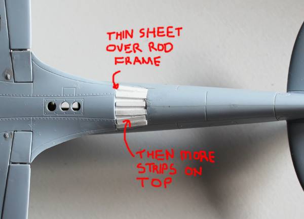
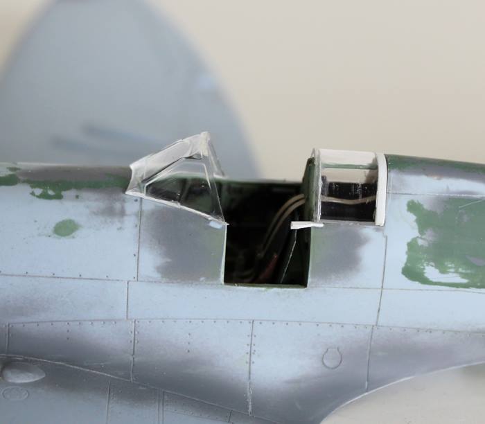
Sanding nearly all done so I’ve started to lay in the front and rear cockpit canopy sections.
The windscreen section is the spare part from the Seafire 46 and the rear section is the standard part from the Mk XIX kit.
Looking at photos and comparing the rear section, I think, fitting per the XIX kit, it gets positioned too far back. To fix this I’ve added a couple thin sections of plastic card at the rear and a thin section of clear sheet on to the front edge. These bits of plastic sheet were attached with superglue, sanded down, polished and then the complete part was dipped in Klear. Adding the extra length has brought the front edge of the rear section into alignment with the seat frame and bulkhead. It looks much better in my view. I intend to blend the rear section in to the fuselage more and then scribe new slide rail channels into it at the correct height. Then, during painting, I’ll paint over the lower edge, including the rails, to reduce the height of the remaining visible plexiglass.
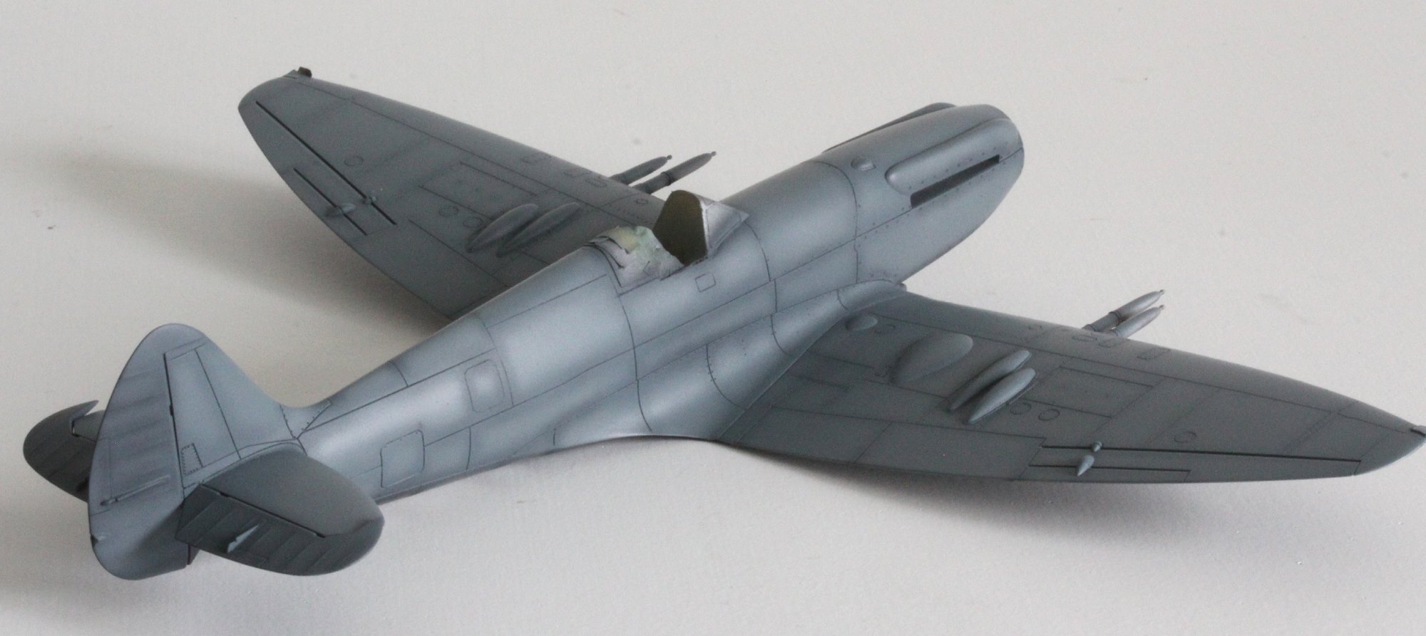
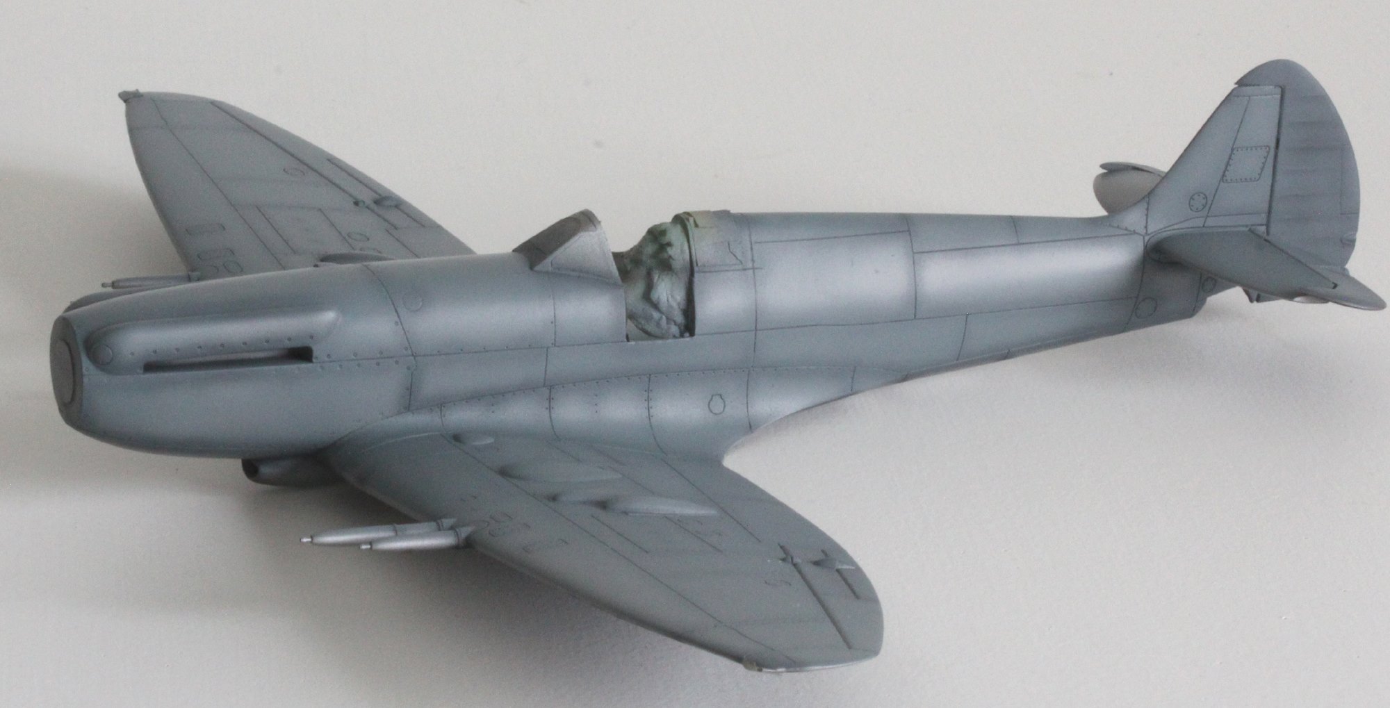
Build is all but done:
It’s been almost a year – due to all that sanding that was needed, and a new job. And time out while I built a Mk Vb – see here. But I thought I better get this finished….
Progress to date: the airframe is together and pretty much sanded ready for paint (thankfully!). This is the start of the best bit. I prefer the painting stage over the build stage any day. Cannon barrels are after-market resin.
The first coat of paint is applied. This is the cockpit interior grey/green. Sprayed on now right at the start of the process it should show through the clear parts and give the inside of the cockpit framing the correct cockpit colour.
Prep for Paint:
To keep up the lightening pace… a little progress this evening.
Second splash of paint. This is my primer layer, Alclad 2 Dark Aluminium. When it’s dry, and I have time, I’ll check over the surface for imperfections and may be re-shoot a bit if needed. But the main point of this layer is to provide the bare metal for the chipping effect – which I promise (fingers crossed) will be lighter than I normally achieve.
I can already see it’ll need a bit of polish and attention (more bleedin’ sanding!).
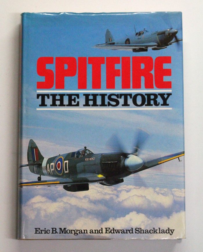
Another Purchase; Spitfire The History by Morgan and Shacklady. Been after this for a long while…and ended up buying it from a chap who’s house I passed every day on the way to work!
Still Prepping for Paint:
Still faffing with joints that won’t disappear. So having got bored with that I started to look at what colour to paint it – or moreover, which paints to use.
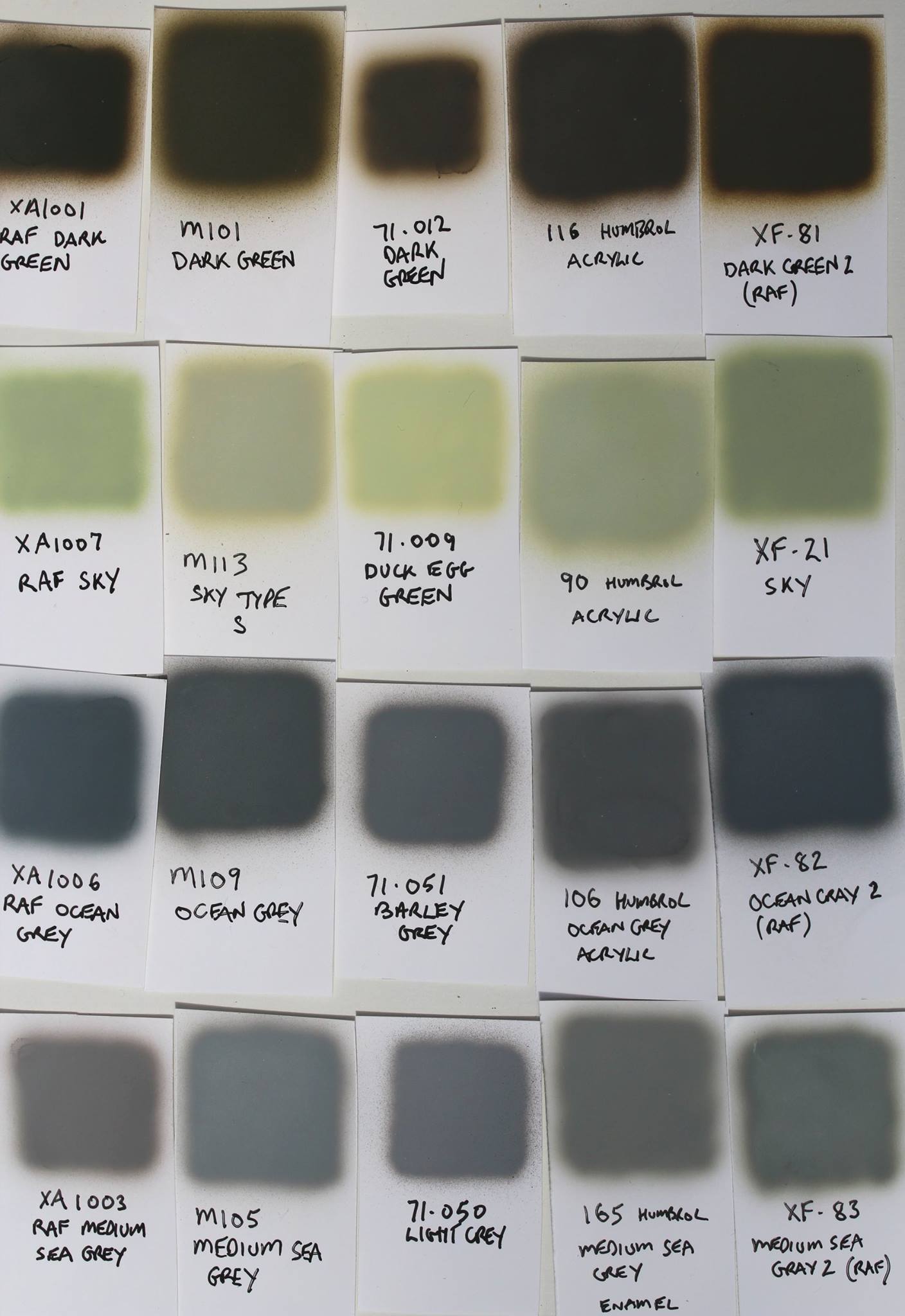
The colour scheme will be standard RAF late war of Dark Green, Ocean Grey and Medium Sea Grey. I decided to review the various paints I had kicking around for these colours, and while I was at it, I through in Sky too.
Here are my choices…
- Xtracrylix,
- Phoenix Precision,
- Vallejo Model Air,
- Humbrol acrylics and
- Tamiya.
On the swatch sheet below, from top to bottom: Dark Green, Sky, Ocean Grey and Medium Sea Grey.
All were sprayed on to white gloss coated card at the same pressures. All were thinned in order to improve spraying. Incidentally, the worst paint to spray was the Humbrol acrylics. But I suspect I am just not using the right thinners.
Here’s my results:
I compared these self-made swatches against the colours given on the plate at the back of British Aviation Colours Of World War Two, The Official Camouflage, Colours and Markings of RAF Aircraft, 1939-45, published by Arms and Armour Press.
In my opinion (and there are so many factors here that can sway what I actually see that it can only be a personal opinion) here’s what I see when compared in natural light:
- Dark Green: Best match = XA1001 and M101. 116 and 71.012 are close and XF-81 is the worst. XF-81 appears too olive in hue to me.
- Ocean Grey: Best match = XA1006 and XF-82 although both are a little too dark. M109 is close behind, but 106 and 71.051 don’t have enough of that ‘blue’ tint.
- Medium Sea Grey: Best match = 71.050 and M105 (Vallejo’s 71.049 ‘Medium Sea Grey is way to dark). XA1003 is OK but lacks a slight ‘blue’ hue. Both XF-83 and 165 are almost ‘green’ in hue and don’t look right at all.
- Sky: Best match: M113 and 90, and then XF-21 is close behind. There’s not much between these three. XA1007 and 71.009 are both too bright.
I don’t wish to start off a debate here. This is just part of the process of making this F.21.
My choice will be… a tough one. By my own review I should use XA1001, XA1006 and 71.050. But I used Xtracrylix on a Mk Vb (see here) and it didn’t work out that well with my chipping method – although I do like the colours. The Phoenix Precision colours look OK and spray very well, but the enamel won’t work with my chipping process either. Humbrol sprays really bad. When I do come to spray the model with its camo coat I’ll be adding in white and yellow to the grey and green to get a faded look – so there’s room not to be too critical.
I don’t yet know which I’ll use yet. I’ll let you know when I get there.
Chipped Prop Blades:
In quite a few of photos of ‘wooden’ bladed Spitfires, there appears to be what looks like metal cladding applied in a thin strip on the prop’s leading edge. This gets chipped. As an example of what I’ve seen, here’s a photo of Mk XIX… On that lower prop blade you can almost see the continuing inner edge of the metal running up the blade and at the tip you can see the edge where the chip stops. The effect is to limit the paint chips to the very front edge of the blade.
Painting Starts:
Painting-proper has started; the real fun bit…
Images are not that interesting but show the following layers:
- Cockpit canopy sprayed with grey-green to show correct colour from the inside.
- Primer layer – Alclad 2 Dark Aluminium all over.
- Sealing layer of Klear.
- Tail surfaces primed with Dark Grey (Tamiya).
- Thinned Microscale masking fluid on key areas to simulate chipped paint (not that much done).
- Rubber Black (Tamiya) used for pre-shading all the panel lines and tail surface ribs.
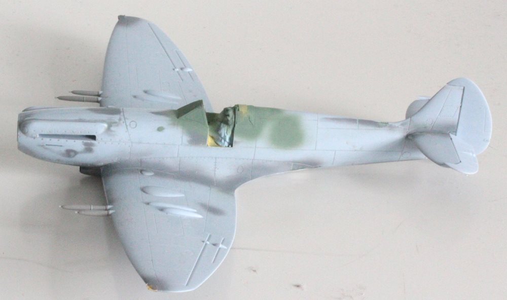
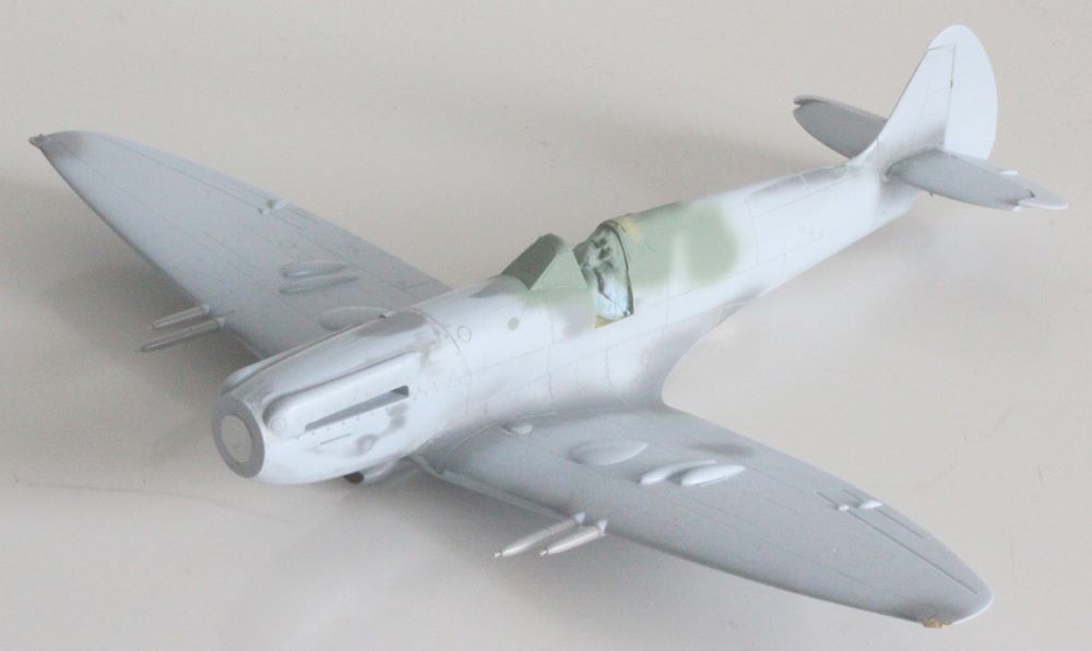
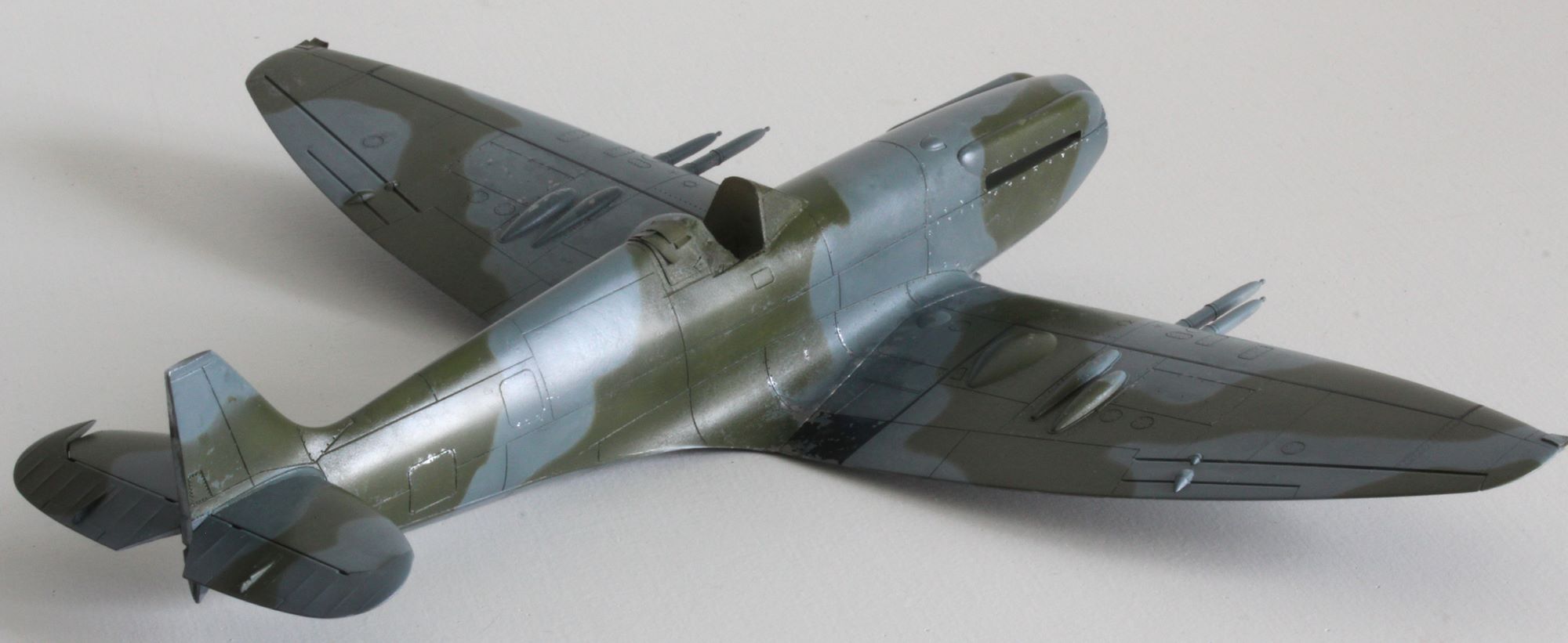
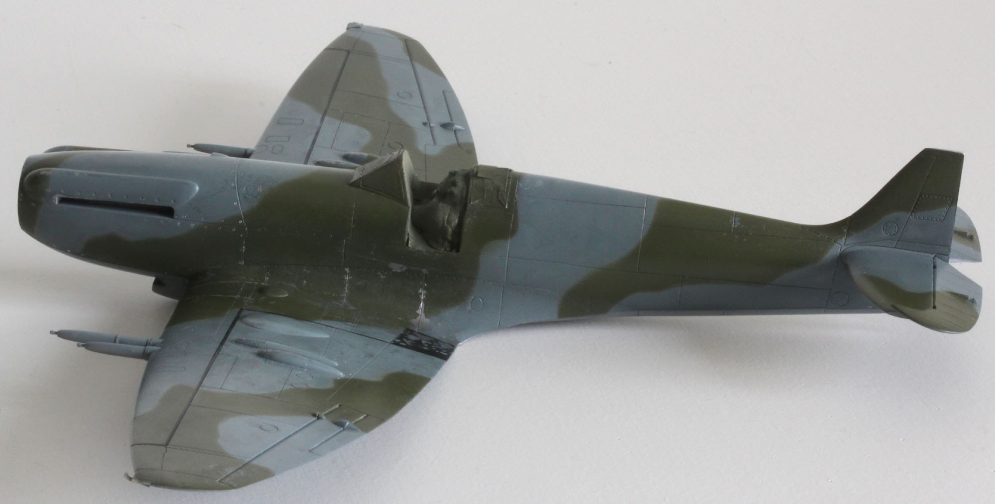
- Base coat of Ocean Grey applied… and then Dark Green. I ended up using Xtracrylix again. I tried to spray it thinly in the hope that chipping would work OK in the end.

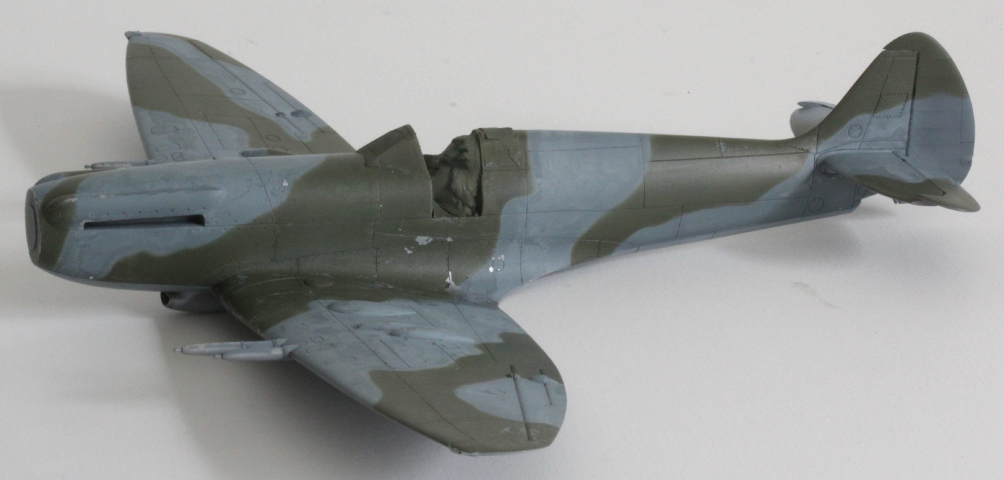
Repaint!:
Things have not gone well:
- I chose to use Xtracrylix again for the Ocean Grey and Dark Green. I love the colour. This time I sprayed very thin coats in the hope that I wouldn’t create a solid ‘plastic’ coat of paint that wouldn’t come off where mask was applied. It didn’t work well. I managed to get some paint off to create the chipped effect but where it came off it came off too much and in most places where I wanted little scrapes and odd patches, it stayed stuck to the model. I had thinned the masking fluid down and I think this is part of the problem too.
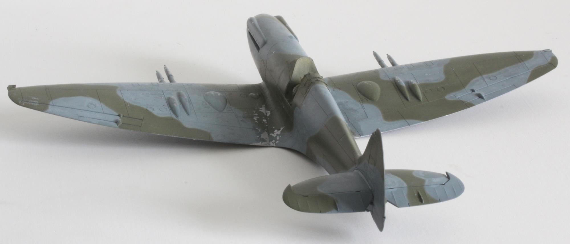
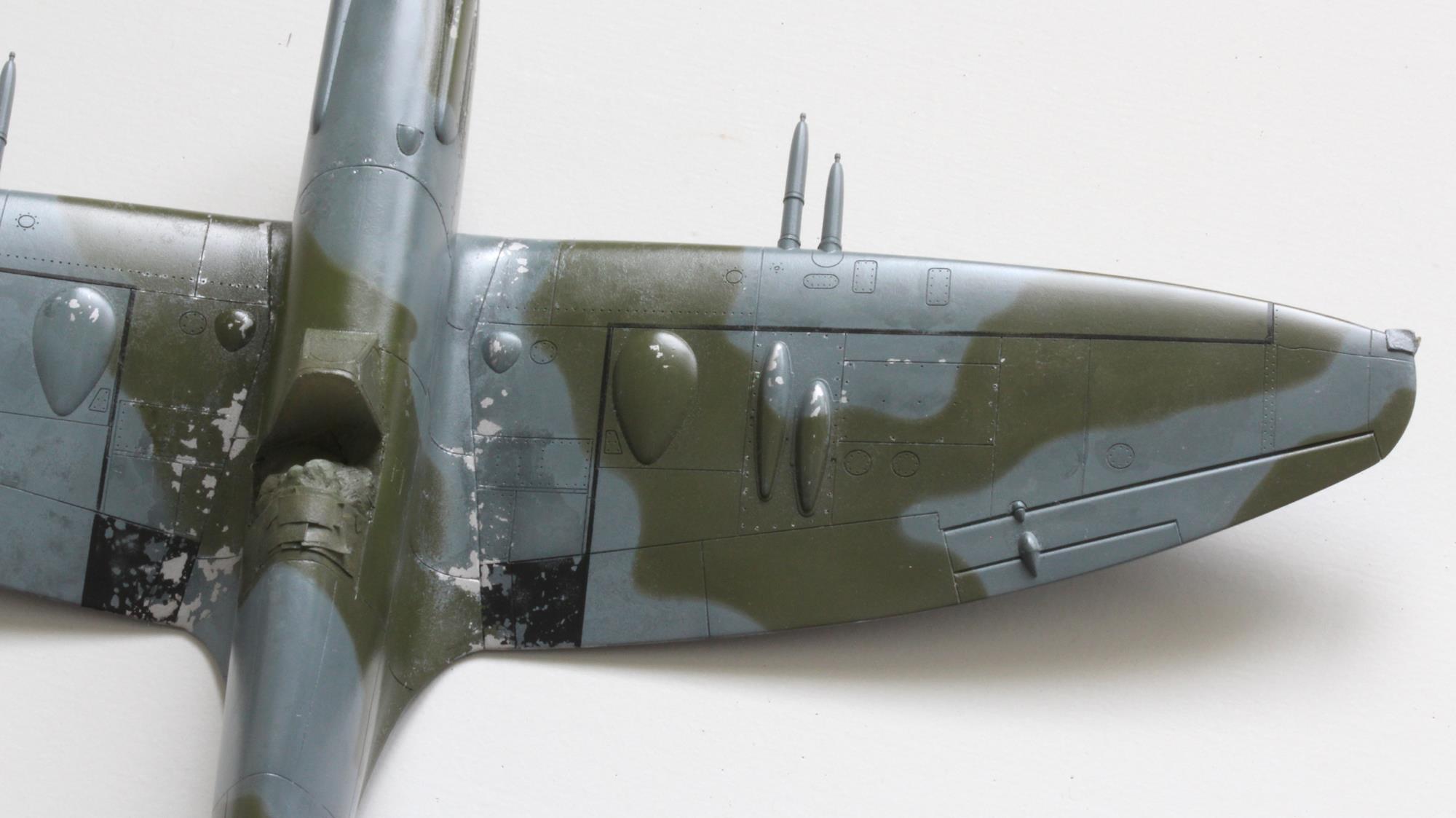
- I tried something new, for me. I used salt on the base Ocean Grey layer followed by a lighter coat to create a mottled and faded look. It looked fine. Then I added the Dark Green and my Blu-tac snakes left their mark contouring the Dark Green. You can see this on the images. Fail. They might disappear with a coat of varnish. We’ll see. I should have waited and used the salt after the Dark Green was applied. The staining from the salt alone would have given me the effect I was after, I think.
- The Tamiya masking tape pulled off the Ocean Grey from the gun barrels. Nothing wrong with Tamiya masking tape, it’s great stuff – I obviously didn’t clean the parts of grease before painting. I fear if I mask off again to re-spray I’ll pull off the Medium Sea Grey from the undersides. Hmmm.
- I did find that attacking the Dark Green with an oven pad (in an effort to get the chipping to work) caused a very pleasing faded look as some of the Ocean Grey was exposed.
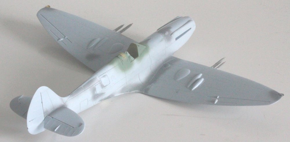
- While I was scrubbing off the Ocean Grey and Dark Green I ended up removing some of the pre-shading before I had added the Medium Sea Grey undersides. This meant I had to re-do some of the masking. The result after scrubbing off the Medium Sea Grey is that I have exposed the Rubber Black. Another fail. Should have sprayed the MSG before attacking the upper surfaces.
Undersides were sprayed with Vallejo 71.050 and look OK to me, mostly…
Next task – fix my mistakes.
Painting Sort Out:
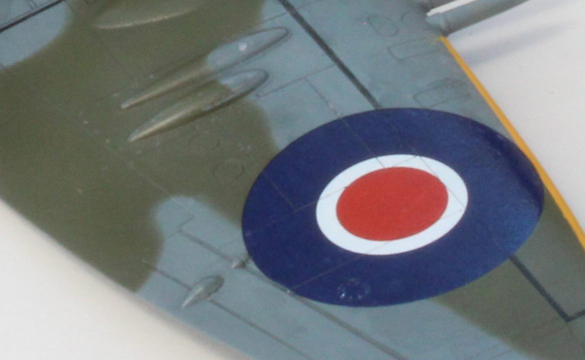
After a bit of a tidy-up, Klear coat and wing-walkways…

Next; yellow leading edges, decals and tone down.
The rudder fell off! But that’s fixable.
And something has fallen off inside and is now rattling around!!! 
The main remaining issue is (assuming there isn’t something else I have missed?) …. I should have used masking tape rather than blu-tac worms. On my best reference the Ocean Grey to Dark Green demarkation lines are very solid, no blurring at all. Fail!
Further Painting and First Decals:
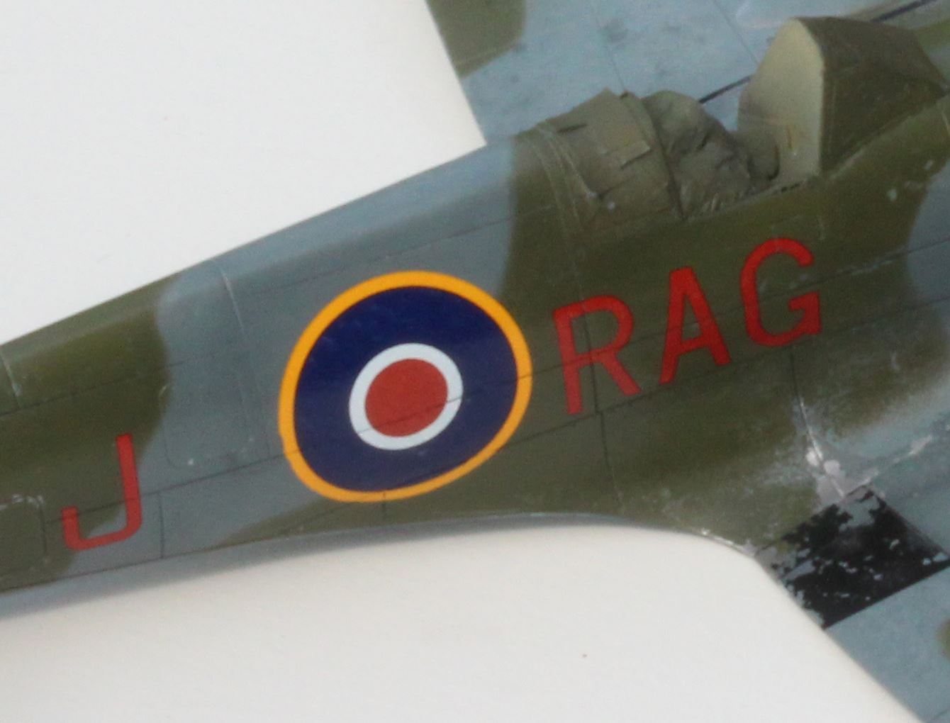
Bit more work… wing leading edge yellow identification markers and decals on. Well, the main ones anyway:
I’m off to research F.21 stencils.
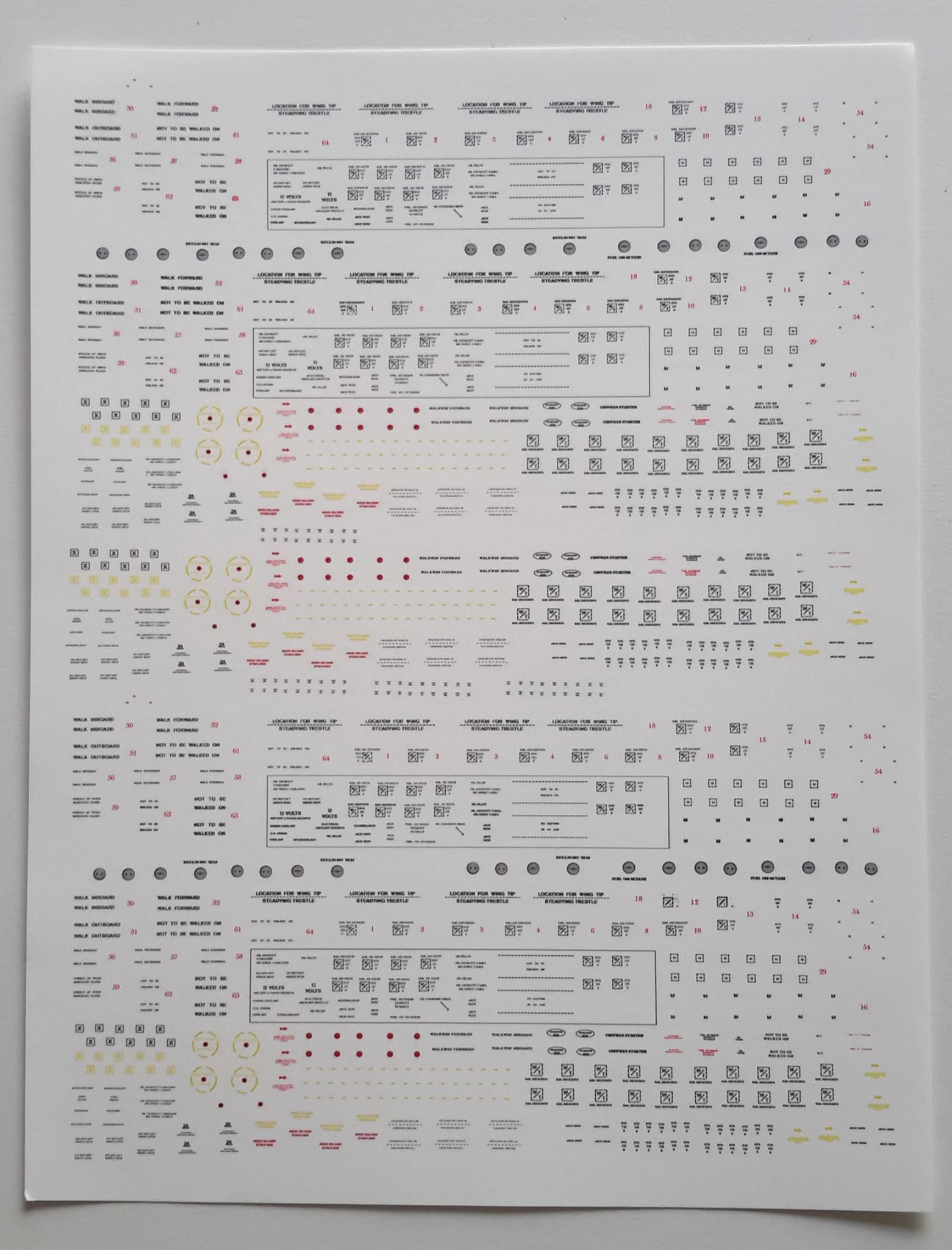
Stencils:
Stencils… Created my own decal sheet – with enough Spitfire stencils to keep me going for a while (this includes the ones I made for my MkXIX. Hopefully I’ll get the stencils added to the Mk 21 tonight.
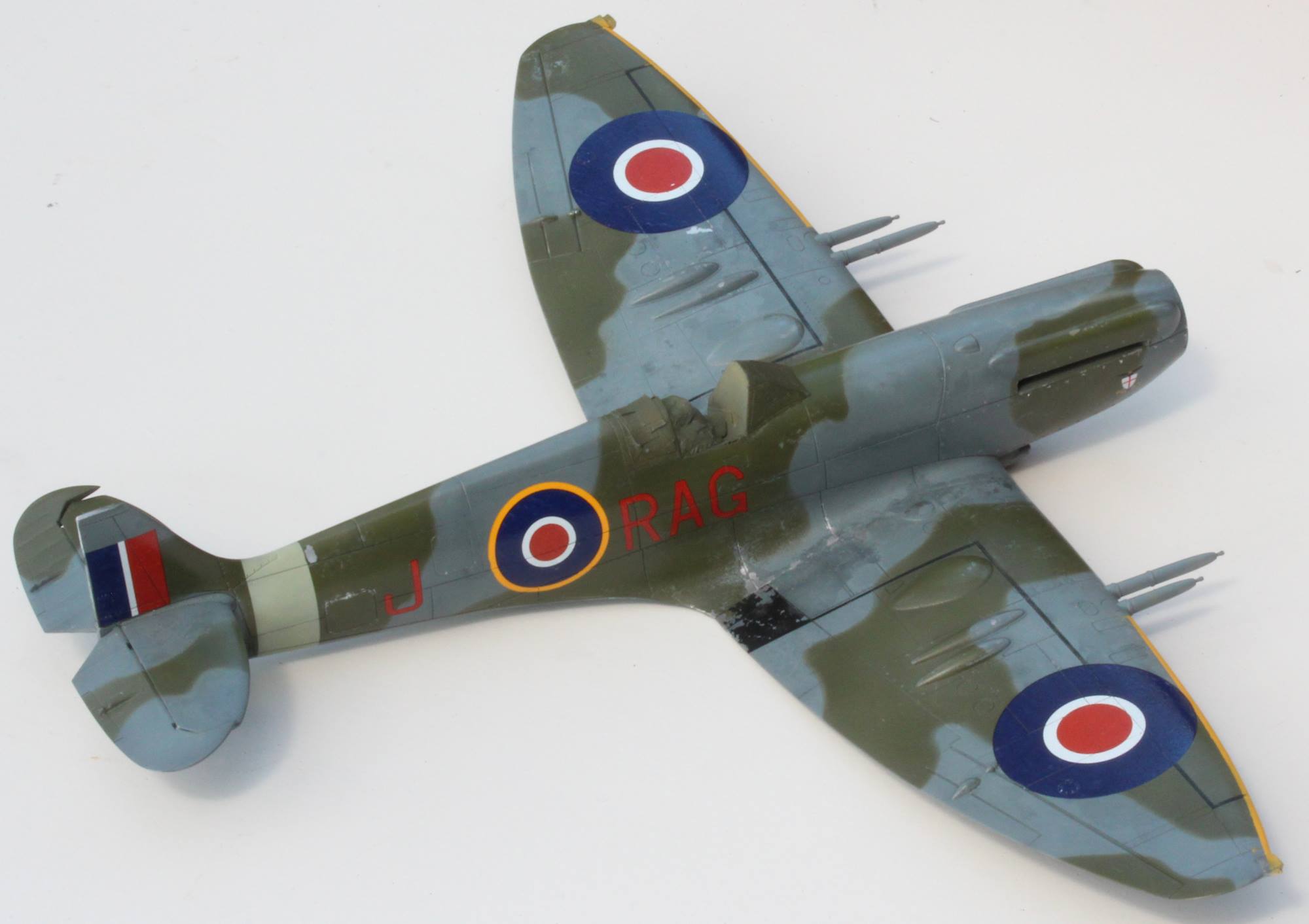
Finished:
Couple of months shy of 2 years and…
Supermarine Spitfire Type 356, Spitfire F Mk 21 of 600 Squadron (County of London) RAuxAF, Biggin Hill, 1947. 100% Airfix, almost.
More photos on Ready For Inspection.
The End.